Microcontroller board design finished
As the title suggests, I've (basically) finished the PCB layout for the microcontroller (and associated circuitry). The main reason I haven't updated at all in the last week is that I've been working on that pretty much the entire time.
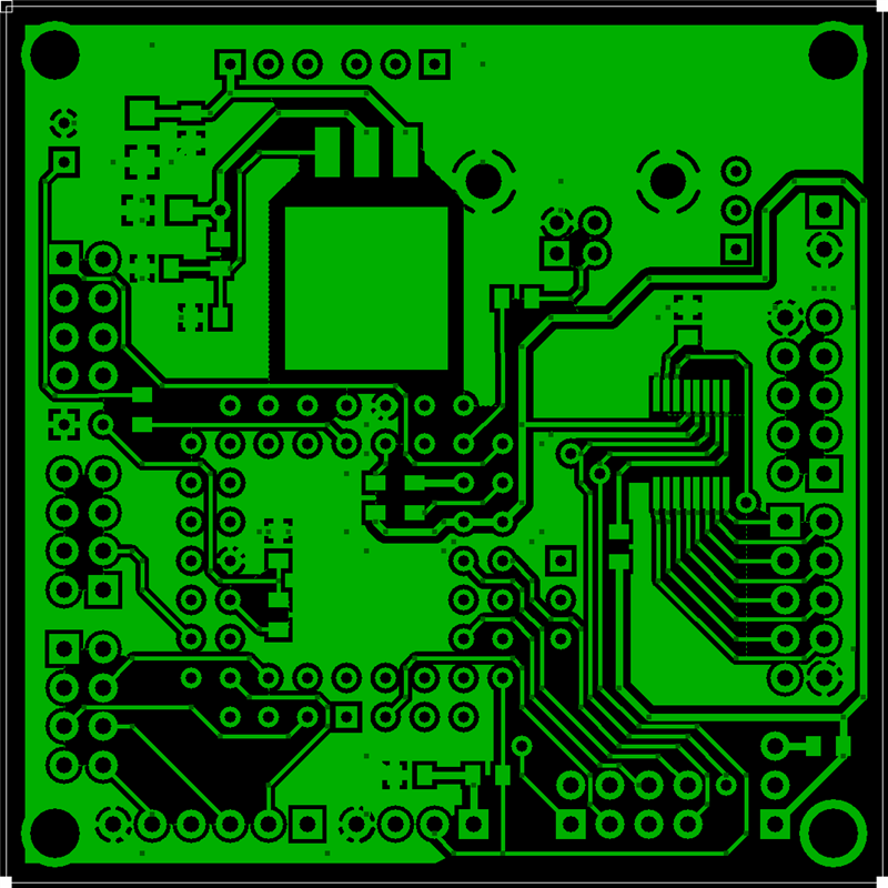
I basically finished the original layout on Wednesday-ish, but then I decided that I should probably put the ADC's on the board, mainly for cost reasons. I managed to squeeze the entire thing into 2.25"x2.25" (the LED driver boards are 1.9"x1.9"). It contains 44 components and 17 headers/connectors.
The biggest component is, of course, the microcontroller. It takes up the majority of the lower left-hand portion of the board and is bordered on two sides by headers.
The big headers J4 through J7 are the chip's 32 generic I/O ports (I'm not including P4, since it's just 2 pins and is only going to be used for the TWI).
J2 and J9 are the two interface ports, TWI and SPI. I use TWI for communicating to the driver chips, as well as the ADCs (which are placed on the same board). I'm currently not using the SPI, but I thought I should put it on there just in case I do.
There are 5 switch headers, so I can just solder some wire to them and place the switches on the frame somewhere. There is also a voltage input header, which will take voltage from the 5V power supply and a voltage/reset output header that will be sent to all of the driver boards. This voltage will be the 3.3V that the driver chips need, as opposed to the 5V that the power supply will be outputting.
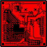
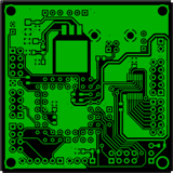
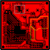
I've provided 3 main images of the layout... The first being the top layer with the silkscreen mask, the second being just the top layer by itself, and the third being the bottom layer:
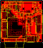


I've also got 2 images with highlighted regions to show some of the subcomponents.
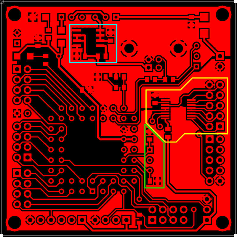


The cyan-colored region is the current limiter for the USB port. We don't want to fry the port (especially on the computer's end), so this is a must.
The yellow-colored region is one of the 8-channel, 12-bit ADC's used for the distance sensors. Each input pin takes in an analog voltage between 0V and 2V and outputs (onto the TWI) a 12-bit digital signal based on the value of the voltage.
The green-colored region is the socket and capacitors for the crystal... not major, but I thought I'd point it out.
The orange-colored region is the voltage regulator. It will regulate any voltage (up to 40V I think) supplied to its input pin down to 3.3V. Also a necessity, since the voltage supply I need to drive the LEDs is 5V.
The blue-colored region is the second ADC. Same as the first, but I need 2 for each microcontroller.
If you haven't noticed (I wouldn't be surprised if you didn't), each layer has 2 different ground planes. The ground planes around the two ADC's are ground planes taken directly from the 5V voltage supply line instead of the digital ground from the USB and other areas. This is suggested by the datasheet for the ADC's for analog isolation. If this screws stuff up (which it might), I can always solder a jumper between the two ground planes to electrically connect them. The lower right-hand corner of the board has a short distance between two header pins of the two grounds, so it should take a very short jumper to accomplish this.
Labels: Design
posted by Jurek @ 11:55 PM
![]()
![]()
0 Comments:
Post a Comment
Links to this post:
Create a Link
<< Home