Pixels galore
What a fun two days it's been.
I got my first "OTJ" injury yesterday. I was stripping the outer casing off some 6-wire phone cord with a scalpel. I got to the length that I wanted it to be stripped to and was attempting to cut off the excess casing. I was holding the wire in my left hand and cutting with my right. I was thinking about how dangerous what I was doing was and that I really shouldn't be when the blade slipped and went into my thumb. I won't get into any details, but it wasn't very bad.
Yesterday, I made 3 pixels out of cardboard, paper, & aluminum foil. The one I used in my first test was a pile of junk and just slapped together, with bad walls (they didn't go all the way up in the corners) so I wanted to make all new ones. Here's the 3 of them all spiffy-like with lighting:
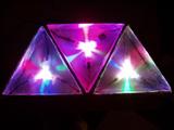
That worked just fine. Here's a video of it all:
QuickTime Video (4.2MB)
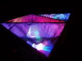
Wonderful success. Only, I ran out of resistors. I had to scrounge to make the 3rd pixel even work. So off to Radio Shack I went today and picked up a few random resistors. I redid the layout on the breadboard, as it was a complete clusterfuck of wires. It's not much better now, but there's also 2 more pixels to deal with.
Videos of the action in action!:
QT Video #1 (3.8MB)
QT Video #2 (3.6MB)
So anyway, the pixels are 5.5" on a side and 1.5" tall. I'm really liking the size of the pixels; They're pretty visible, even from a fair distance away. Plus, it would be easier to make them (slightly). The 1.5" seems more than enough. If possible, 1/2" would be great, then I could hide all of the electronics behind that in a 1-2" gap, leaving the entire structure to be 1.5-2.5" deep in total. Quite nice. I'll have to stop by Home Depot or somewhere similar to look for what I can use for wood. I remember seeing 1x3" and 1x2" pieces there. They also had 1/2x3", but it was meant for stairs and was very expensive.
At this point, I really should design the driver boards and get them off and made. I'm sorta limited right now with what I can do with the driver chips and once I get those, I can test further.
I think I will have to bite the bullet and spend $140 on a new soldering iron too. Dealing with the hassle of trying to find someone to pay to do the soldering will be far worse and I think I would probably end up spending more than $140 trying to contract it out anyway.
I think at this point, I am almost ready to start designing the actual frame for the pixels. I will have to re-evaluate how large I want to make this thing (my previous count of 159 pixels was based on hexagons... it will be slightly different with triangles) and if I want to expand the design at all.
I've also been briefly toying around with the idea of having a main microcontroller whose sole purpose is to generate patterns and delegate information to the other microcontrollers. I wouldn't be able to use the TWI for that purpose, unless I figured out a way to get the other microcontrollers to disconnect themselves from the rest of the LED driver bus, which may be a bad idea in general. There is an SPI bus on the chip as well that I could use. It's still in very rough planning at this point, mainly because I only have one microcontroller to test with.
I found an 8-channel 12-bit ADC (analog to digital converter) chip that works on the I2C (TWI) bus. This would be a much better alternative to the single-channel one I had found earlier. I could use a single one of these for each microcontroller and get good coverage for the whole wall. I might have to order up one for my next Digi-Key order.
All in all, very promising results so far. Once I get a new soldering iron, I can solder up another driver chip and start testing multi-chip communication, which should be fun.
posted by Jurek @ 12:36 AM
![]()
![]()
1 Comments:
Heh dude your colors5.mov looks like the umbrella corp from resident evil ;)
Post a Comment
Links to this post:
Create a Link
<< Home