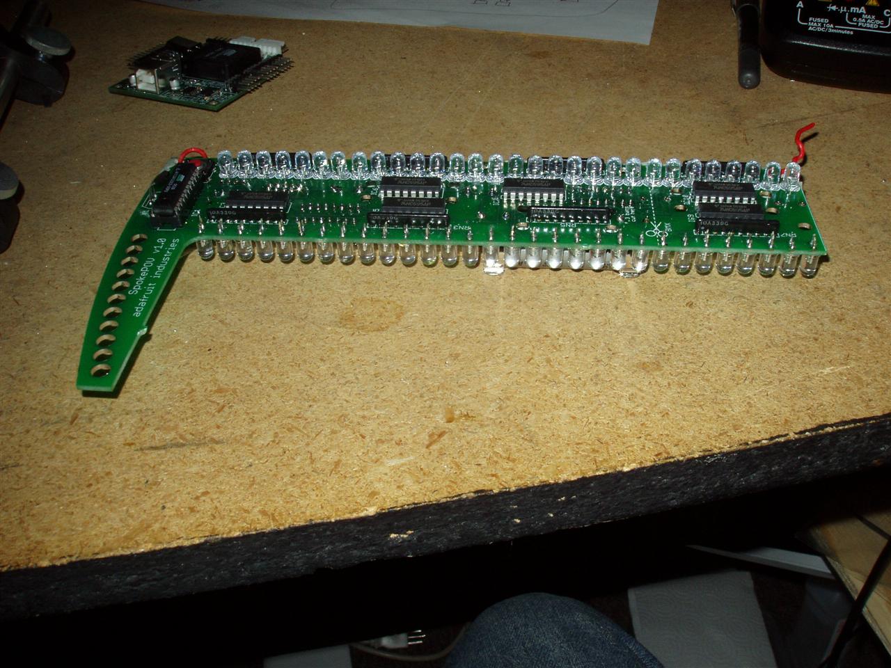
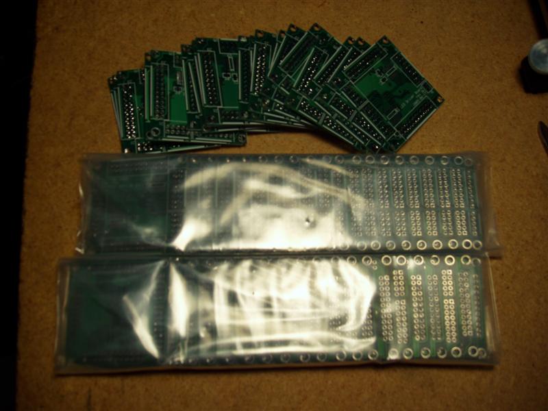
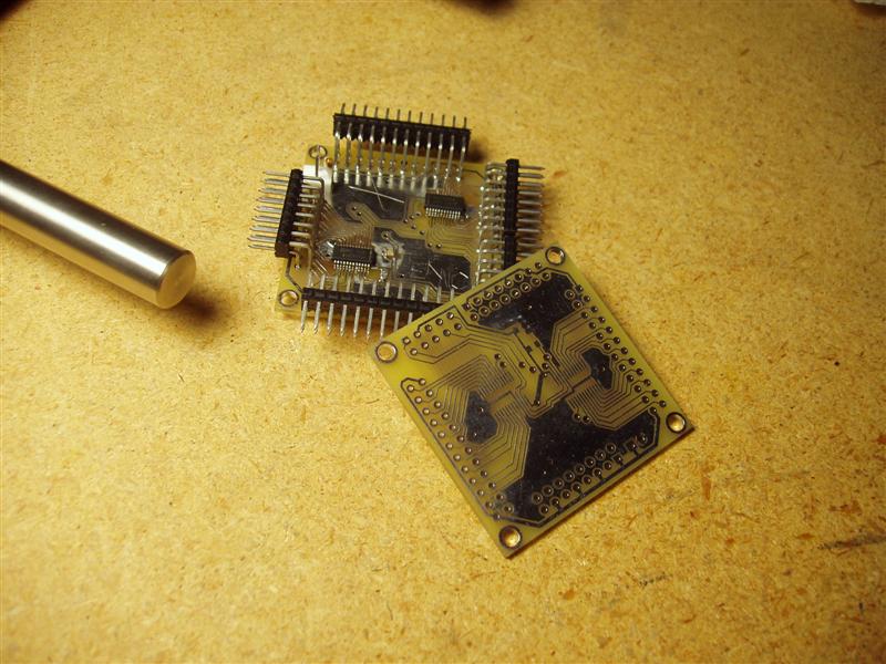
Jurek and the Amazing Techno, Colored DreamWall

Jurek and the Amazing Techno, Colored DreamWall

The title is mostly a placeholder, as I haven't really figured out a name for it yet. This project is a wall hanging that consists of semi-large triangular pixels using discrete RGB LED's and PWM to control intensity levels of each LED, resulting in a 4096-color display.

Tuesday, May 29, 2007

Testing Update

Workspace
This is a fairly small update -- not much has been happening lately, mainly because the 'wall is still at the Center Earth studio.

I bought some rope, pullies, tie-downs, and clips to mount in the workspace so I can hoist up the wall and work on it while it is vertical, but also still have good access to the back of it. When I was building it before, it was always troublesome to shift it around and get at the cabling in the back while also requiring to look at the top of it (for the pixels).

I usually ended up either blocking it up on some pieces of wood or large batteries, which generally left it just balancing there, or horizontal on sawhorses and counter-weighted on one end. I had to counter-weight it because I needed access to the back, which was hinged in the exact middle of the pixels. The power supply shadow box extended beyond that and added a bit more weight, making it more bottom heavy. The counterweights also obscured several of the pixels, making it slightly harder to debug wiring, soldering, and coding problems.

The setup that I'm working on now will get rid of all of these issues. The only problem I think I may have will be with being able to muscle the wall into position. If it becomes a bigger issue, I will have to rig up a block-and-tackle assembly to make it easier.

Pictures when I get it done...


Construction
The gluing has finally finished on the small 20-pixel test box, so I can finally start playing around with different combinations of things (e.g. 3-color LED's, different reflectors, different positioning of the LEDs). More will come with time.


Soldering
There were 2 driver boards that each had a single LED not working, so I spent a little time resoldering the pin on each of them, so they will both hopefully work now.

Labels: , ,

Wednesday, March 14, 2007

Small Update

Soldering

So, I actually got a small amount of soldering done last night and tonight. I got 2 more driver boards soldered up, one of which I tested a small amount. The one I tested seems to be working, for the most part so far. I verified that the chips are all able to communicate with the microcontroller, and that at least one of the LED output channels works for each chip.
Things went pretty smoothly overall with the soldering, mainly because I ordered and was using brand new 0.01" soldering tips. Two down and 4 more to go!

Construction

Very little progress has been made on the for-test 20-pixel box. I have 2 of the10 sides glued on. Things are gong fine with it, just very slowly. I hope to get it to the point where I can test the 3-color LED's relatively soon. I can pull the microcontroller out of the big LED wall to test with until I get another board soldered up.


TTFN

Labels: ,

Saturday, February 24, 2007

Miscellaneous Progress

Test Module
Progress continues on the smaller test module that I mentioned in my previous post.
I've got the pixel divider walls and the backing glued together, and I tested using aluminum tape on the floor of the pixels. As it turns out, Home Depot stopped carrying the 2'x4' 1/8" white marker board, and now only carry a brown version of it. It's not nearly as glossy (plus, it's brown), so I'm attempting to use the aluminum tape as a reflective agent on the floor as well.

The small number of pixels, combined with the assembly method I have, actually makes this small one not very easy to keep "true", as far as the pixel shapes are concerned. There are only 2 triangles that end up being "perfect", and they're not adjacent to each other (only kissing), so everything kinda wobbled around a little, until I got the floor glued to it.

Soldering
I started into soldering up another driver board, mainly to get myself back into things. The only components I got soldered onto the board were 2 resistors and 2 capacitors. The tip I had used for the first time around is basically useless for the very small-pitch components. It's gotten so built up with debris, and has probably had the tip melted or broken off, so it's not nearly as fine as I need it to be. I'll need to order about 5 of those bad-boys to keep me in stock.

Design
I just got a new tablet PC on Thursday and finally got that up and running. I got all of my development tools installed, brought the tablet over to the work space, and hooked it up to the processor to make sure everything works. It still does, thankfully, and having a small portable communication medium for programming it will be a great help. I also put the visualization Python code on it and tested it out for performance. It runs at about 1/2-1/3 the speed as my desktop, peaking at about 25ms per frame at the highest resolution, so I think it should be fine for "production" use.

I need to start writing more with that code, so other people can start playing around with it. It's pretty rudimentary right now, but I hope to get it to the point where patterns, shapes, text, etc. can be made as individual files and then loaded on the fly.

Media
OK, so you gotta start out small, I guess. I was contacted by one of the writer/director/producers of an up-coming short show called Center Earth about using the technowall as part of background for various scenes. Shooting is slated to start in mid April, and the wall will probably be needed some time in May-ish. There's not much more to say about it yet, but I'll keep everyone posted about progress with it.

Labels: , , ,

Sunday, October 22, 2006

Mondo Update

LED Segments

I've gotten 20 more of these done! That puts me at 152/240, with 2 more needed for this first module. I will probably do them a little tonight and then finish them up Monday or Tuesday. After that, I can stop for a while (thankfully). My fingers are pretty sore and sensitive from the heat and metal.
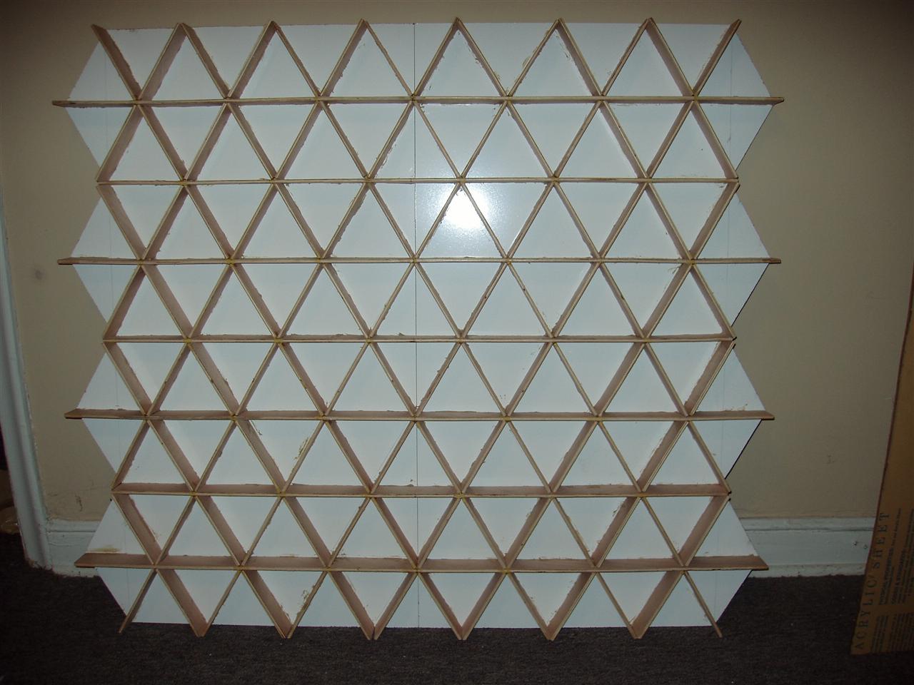
Assembly

I had to remove one of the pieces of contact paper from one of the pieces of acrylic, because the velcro I had been using just wasn't cutting it (or, more precisely, was burning it from the hot glue). I bought about 30ft of self-adhesive velcro, 3/4" thick, and used a fabric cutting wheel to make nice, straight cuts along it (gotta cut it into thirds!). This works wonderfully, as the adhesive on the velcro is unlike anything I've ever seen. It stick amazingly well to basically everything.
Anyway, I got a new piece of contact paper put on the acrylic and spent a couple hours today putting the velcro on it. The first (bottom) piece of acrylic is now completely done and looks "OK". I say "OK" because there are still air bubbles randomly throughout it and a few minor holes. Not the best job in the world, but I'm now under a small time constraint (read below).

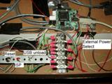
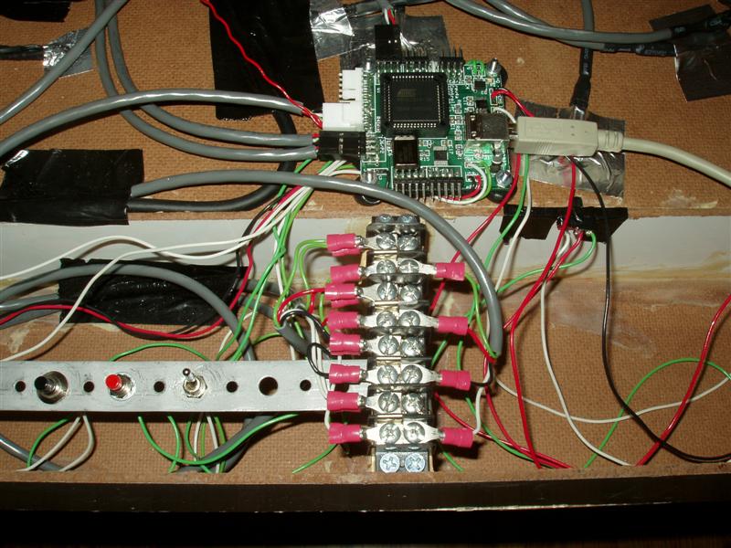
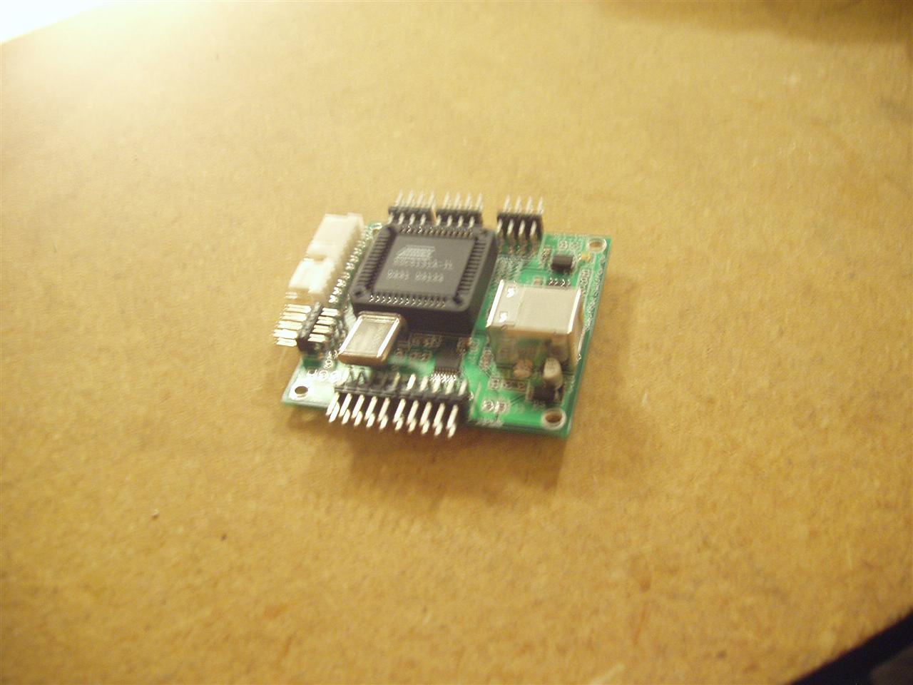
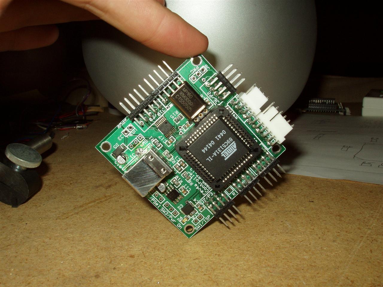
I finally got the processor board mounted to the wall, along with the different switches for reset, ISP, USB unload, and power supply selector. The only switch I have yet to mount is the main on/off switch. The switch I've been using isn't the one that I plan on using, so I haven't made a hole for it yet. Actually, I'm not sure if I will even use a switch right away. It's not entirely needed (the main power switch works fine) and especially not right away.

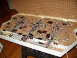
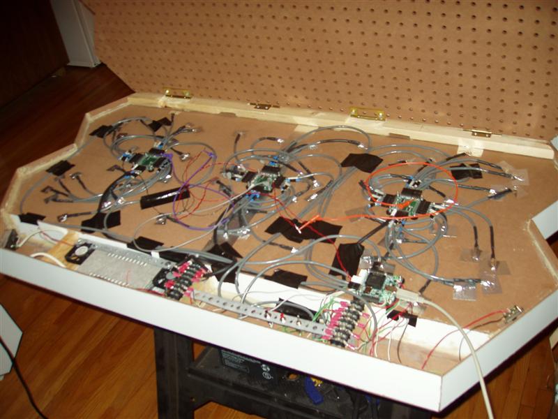
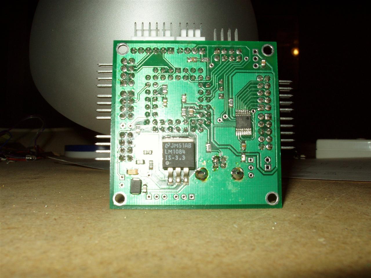
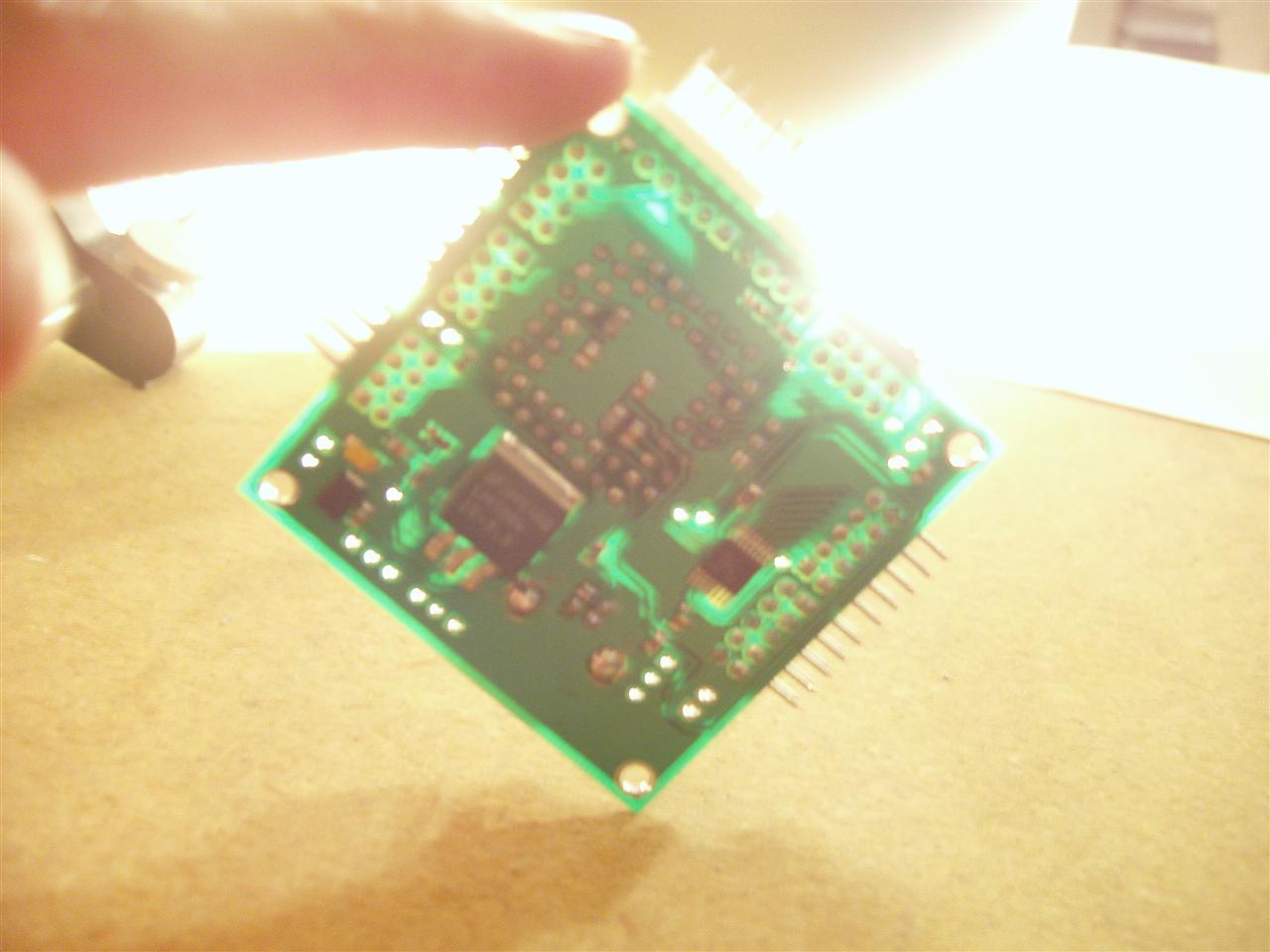
Here're some pictures of the guts behind the pixels (and man is it messy!):
InternalsPower SupplyProcessor MountProcessor Mount, with labelled switches


There're still plenty of wires to add, such as power & control cables for the "upper" 3 boards, as well as finalizing the cabling for everything. You can see in the overhead shot that there are orange, purple, and grey clip cables attached to random squiggly wires. These are the reset lines for the boards, and I'm going to be tying them to power directly, but I don't want to route the cables completely yet. Once I get all 6 driver boards working, then I will finish that step.


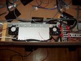
The processor and switches are mounted on the opposite side as the power supply, with enough room to take up the two remaining compartments (the angled compartment on the end is barely used).

You can also see the two fans (poorly) mounted for cooling. The one on the right blows into the area, whilst the one on the left blows out of it. They probably don't work too well, considering that there are large open areas for the air to simply escape through, instead of cycling the hot air around the power supply. I'm still not entirely sure how much cooling will be needed. I started doing some temperature measurements without the fans running, but the battery for my multimeter died, so I couldn't test any more. After about 3-4 hours of running 1/2 of the pixels in just 1 module at about 20% capacity, it rose from 74F to about 95F. Once I get everything running, I'll try turning all 120 pixels of module 1 on full white and just leave it there for a couple hours. If all goes well, it shouldn't get much above, say, 130F, which is still fine as far as I'm concerned.


I cut a small notch in the internal wall for the power supply source switch, which fit nice and snug in there. It's currently only being held in by duct tape (I don't think "duct tape" is even used by HVAC technicians on ductwork), but that can be "enahanced" with glue later. The other 3 main switches are all mounted on a simple strip of galvanized hanger strap. The large holes worked perfectly for the threading, and it's stable enough for what I need.
The large terminal block looks very similar to the one next to the power supply (which is used for power!), but is for the TWI bus. This seemed like the most effective method of breaking out the bus from the processor to the 6 boards that all require the same signal.

Coding

I've begun coding up a few basic tranform functions to apply to the wall. Currently I have:
  • Inversion (inverts the colors of all the pixels... red -> cyan, black -> white, yellow -> blue, etc)
  • Shift up/down/left/right (shifts all pixels up/down/left/right 1 row)
The inversion can be enhanced to only invert certain channels (e.g. only the red channel)
The shifting functions can either roll over the shifted-out pixels, or just shift in a blank (black) pixel.
If you combine "shift up" with "shift left", for example (or "shift down" with "shift right"), then you get a tranform that shifts all pixels along the upper-left/lower-right axis (there are 3 axes with triangles, not the normal 2 with rectangular ones!). Likewise, combining "shift up" with "shift right" (or "shift down" with "shift left") translates the pixels along the upper-right/lower-left axis.
Simple, but powerful stuff.

Other potential transform functions are
  • Average (averages the surrounding 3 or 12 surrounding triangles)
  • Rotate (rotates the pixels 60 or 120 degrees about a given pixel)
  • Fade (slowly fades the pixel from its current value to black (or white, or any given channel!))

I managed to find, in the documentation, the status bits for controlling the speed of the TWI bus. I think, by default, the transmission speed is set to 62.5 kHz. By setting the speed bits to the fastest setting (266.6 kHz, a 4.3x speed increase), I was able to increase the framerate of the wall by about 50%. This was a very welcome change, indeed. Hoo-ray!


Announcement

Some of you may have been wondering why there has been a huge bump in the progress in this project over the last 2 months. Indeed, I've put in 27 hours this previous week, and 85 hours since September 1st. Well, there is reason for this, and quite an exciting one (for me, at least).

Now that it's official, and I've committed myself time-wise for it, I feel I can mention that the "technowall" (NOT the official name!) will be part of the upcoming (Artist's reception/opening is on November 17th) video game art show at Altered Esthetics: "Level_13: Bonus Round!". Their address at the time of the show is:

Altered Esthetics
1224 Quincy St. NE
Minneapolis, MN 55413

This is just off Broadway and Central; for those that need directions, please consult your favorite mapping website. If you need more information than this, please contact me.

I will only have the 1st module done, and won't have any computer interface ready, but I will be spending a fair amount of time with coding to get various random (and not-so-random!) patterns working. The pseudorandom seed switch (see the October 10th post) should keep everything random enough for my needs.

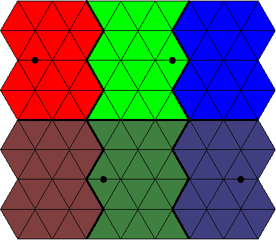
I have already designed several patterns, as well as a few other neat designs, with more to come (hopefully). If anyone wants to try their hand at designing something, here is a PNG template that I've been using:


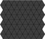
Please email any creations to me! I'd love to see people's creativity with such a small (and oddly-constrained) resolution!

Exciting news!

Labels: , , ,

Friday, August 04, 2006

Half done with soldering!!!

Wheee! Finally topped the 50% mark on soldering of the LED segments! 122 of 240 done.
  • 30/28 (107%) 12" segments
  • 27/68 (40%) 8" segments
  • 41/84 (49%) 6" segments
  • 12/24 (50%) 5" segments
  • 10/20 (50%) 4" segments
  • 12/16 (75%) 2" segments
  • -------------------------------
  • 122/240 (51%) segments total

Labels:

Saturday, July 22, 2006

Progress Update

Wow, 3 whole weeks since the last post! Man, people might start thinking the 'blog (and project) is dead.

LED soldering
12 more done, making 112 of 240 (47.6%). I've made some small progress on making more "supplies", like twisted pair sections, heatshrink lengths, and LED & resistor lead trimming, but haven't started soldering any new ones yet.

Construction
I've made a bit more progress in this department (probably more so than the soldering).

I finished cutting one of the two back pieces of pegboard and attached it, via hinges, to a spare piece of wood from the previous construction attempts. This marks the very first metal used in this new design! The hinges split the module horizontally, so the two pieces of pegboard will pivot the same way as well. The hinged back provides me access to all of the electronics once it's done.
I still haven't entirely figured out how to secure the other end of the pegboard yet. The piece that's cut is on the top, and this piece needs to be load bearing. This means that I need to make it secure to the other floor and not just the sides (as they're just glued to the internal floor and provide no structural stability).
My current thinking is to attach several L-brackets to the pegboard and a few to the internal floor as well. Then a metal dowel could be fed through a hole in one side of the sidewall to latch everything together. The only problem is that the L-brackets have to be very small, as the gap is < 1".

Also today, I got 3 scrap pieces of wood (same scrap wood that I used to attach the hinges and pegboard to) glued to the bottom side wall, to make a region for the shadow box. This shadow box, if you may remember, is going to hold the power supply.

That is all for now. The glue is drying as I type, so I'm about done for today. It needs a good 24 hours to properly cure.

Labels: ,

Tuesday, June 27, 2006

Minor Update

This is a small update to reassure people that the project isn't dead.

I've finished the next batch of 12 LED segments, so that brings the grand total to 100!!
This tops 40%.

Yay milestones.

Labels:

Sunday, June 11, 2006

More soldering and gluing

Soldering
12 more (2") LED triplets soldered. 88 done, 152 to go. The 2" sections were kinda tricky, because the wire length was so small and the heatshrink tubing needed to be a certian length just to go over everthing properly. I ended up having to rearrange a few steps in the process to get everything assembled correctly.


Gluing (a.k.a. Construction)
I cut and glued 4 more pieces to the outside of the 1st module. They were all 3"x5.5" pieces. That leaves another 10 pieces on the outside zig-zag part left to cut and apply. For this module, I also need to make room for the battery pack, so I have to extend the bottom side pieces an extra bit, plus have a second long piece on the bottom. The exact dimensions are yet to be determined (I haven't been ambitious enough to sit down and do the measurements). It involves angles and what-not so it's not entirely nontrivial (yay double negatives! Me fail english? That's unpossible!).

Parts
I also ordered 170 2x2 connector housings (sockets) and 500 crimp connectors. The connectors weighed in at a whopping $1.28 each, so the total order ended up being over $250 for just those items (the crimp connectors are very cheap).

This last Digikey order put me near $5k ($4.8k). Lots more to come in that department though. Yet another milestone, I guess. Or something.
*watches as his wallet bleeds more*

Labels: , ,

Thursday, May 25, 2006

Booooo-ring

76 done, 164 to go... woooo... I can hardly contain myself.


On more of a constructive/productive note, this weekend, I sat down and figured out just how many of each length I would need. I drilled a couple holes in the board and zip-tied a driver board to two of the areas to be mounted. With 6 driver boards per "module", and with the layout as it is, there are 2 different shapes of sections, with 8 of one type and 4 of the other.


In the image above, which shows a single module (2 of them, remember), the 8 sections that are alike are the two different shades of red and the two different shades of blue. Doubling this makes for the total needed for both modules. The other shape is the two green regions, doubling again gives 4.

So anyway, back to the length requirements, there are two lengths to the LED triplets that I have been making. The first is the twisted-pair wire going from the resistors to the LEDs. These are all 7" long and will be entirely inside the pixel. The remaining length is from the resistors to the driver board header. I am using 4-conductor wire for this and the measurements required are as follows: (cut length, before stripping or soldering)
  • 28 pieces @ 12"
  • 68 pieces @ 8"
  • 84 (!) pieces @ 6"
  • 24 pieces @ 5"
  • 20 pieces @ 4"
  • 16 pieces @ 2"
For those of you following at home, this comes to 1616", or just under 135'. Add in 720 (3 needed per triplet!) 7" twisted-pair wires, totalling 5040" (420'), that makes ~555' of wire needed. This is about 2.3' per pixel. Far less than some *ahem* other people's projects.

What I currently have soldered:
  • 30 pieces @ 12" (2 more than I need, I think I'll make due... probably make 2 fewer 8" pieces)
  • 17 @ 8"
  • 29 @ 6"

Yay slow progress...

Labels:

Saturday, May 13, 2006

Slow progress

Sorry for no updates in a while. I was out of town for work for a week and had a few other things going on the following week.

I've got the next batch of 17 LED triplets done, so now I'm up to 64 of 240 done (past the 1/4 mark!).
I bought another 300 feet of 2-conductor wire and another 70 feet of heatshrink tubing (all for a whopping $30! Gotta love Axe-Man). This should keep me going for a little while anyway. I will need to order some more LEDs soon, as well as some more 2x2-pin headers that connect to the driver boards.

Whee!

Labels: ,

Saturday, April 22, 2006

Progress Update

LED Triplets
17 more done, leaving 193 left to go. I probably won't need many more triplets with 12" 4-conductor sections. They're quite long and way more than I need for most of the pixels.

Construction
I've made 60 holes (half of what I need) in the section I have (mostly) constructed. One per pixel, each slightly larger than 1/4". The largest drill bit I have is 1/4" and one LED head fits through just fine, but I need to feed the other two LED heads through as well, the last of which also has 4 wires to contend with as well. A few swipes with a circular file slots the hole well enough to fit everything fine.

That is all. Nothing major, just more busywork.

Labels: ,

Saturday, April 08, 2006

Slow week

Yeah, yeah... sorry about no updates. This week has been a little busy for me and I didn't have a whole lot of time to work on anything until today.

LED Triplets
I've finished the batch of 14 I was working on, so now I'm up to 30 of 240 done (12.5%).

Miscellaneous
Now that I have at least 20 LED wire segments, I'm going to stop working on construction and soldering for a bit. I need to verify that the TWI and the driver boards work correctly. The boards each have 4 driver chips and each driver chip can drive 5 pixels, so that gives me 20 pixels per driver board.
So all of my work for a while will be coding and wire crimping (not a whole lot of this).

Once I get the communication working properly, then I can continue on with everything else.
Hopefully, there won't be any major snags. I am prepared for one or more of the chips and/or boards not working properly, but if none of them work, then I'm going to have a lot of testing and re-engineering to do.

If all goes well, I'll have some nice, pretty movies of everything working properly in a week.

Labels: ,

Sunday, April 02, 2006

More updates

LEDs
16 of 240 done... decent progress on the next 14


Construction
I've got both the backing pieces cut, along with the zig-zag edging on one side of each of them. I also attached them to the lattice with liquid nailz. Perhaps it was a little overkill to use that over wood glue, but I wasn't entirely sure how well the wood glue would adhere to the marker board; it's pretty smooth and wouldn't take the glue like normal wood would (hah!).

I ended up buying another dozen (!!!) clamps to make sure the wood was aligned properly as the glue was curing. They aren't light, so it made it quite awkward to handle the wall while it was drying (I had to flip it over after gluing and clamping it to make sure that the marker board properly stayed flat against the lattice).

Here's the progress so far:


It's decent and pretty sturdy now. Before, it was a bit flimsy and I had to be careful where and how I moved it.
There are still tiny air gaps between the floor and the lattice here and there, but a little silicone or caulk will tighten all that up. I'm not entirely worried about it, because the aluminum foil will be covering everything up anyway.

Labels: ,

Friday, March 31, 2006

LED triplets

11 done! 229 to go!

Labels:

Monday, March 27, 2006

Construction and LEDs

Construction
I got 1/2 of the inner wall pieces cut (enough to do one of the sections) and glued this weekend, despite having a nasty flu. On Saturday, I glued everything together and let it cure overnight (in my kitchen, even! I had to climb over the top of it just to get to the bathroom).
I have to say that it turned out quite nice. I was slightly worried about the 22" pieces (4 of them) on the edges, as they only had one notch in them and nothing to really "solidify" their orientation. When I had the pieces unglued and just interlocking, they tended to wobble around a bit. I made extra sure of their orientation as I was gluing them and it turned out pretty well. Still no pictures yet (I'm going to have to get some webhosting at some point), so you'll see it when I get to it I guess :D.

I've updated the progress bar to 18.5%, as I still need to attach the first backing piece as well as the exterior walls and the outside floor piece. It might be a little conservative, but oh well. I found some really nice material to use as the pixel floor. It was some 1/8" stuff I initially bought for the exterior walls. It's marker board and has a nice white, shiney surface on it. One that should work excellently as a reflector, rather than the pieces of paper I had envisioned before. I should need 2 pieces for the floor for each section, totalling 5 that I'd need for the whole assembly. (I should only need 1 for both sections for the outer walls). It cuts moderately OK and is decent to clean as well.

LEDs
I got most of the next batch of 14 triplets worked together. I have all of the 4-conductor wire stripped of casing (but not each individual strand). My fingers were hurting too much from stripping, so I ordered up a wire stripper from DigiKey, along with 1250 3/16"x1/2" pieces of heatshrink tubing (about 52 feet) for the LED connections. I figured this would be easier and more cost-economical than buying tons of 1' pieces and cutting them all myself.


The progress bar is updated to 4.5%. After 16 are done, I will be at 6 2/3% done, so this may be slightly conservative as well.

Cheerio!

Labels: ,

Tuesday, March 21, 2006

Update

Construction
I made decent progress over the weekend using the new method. I completely cut up a 2'x4' piece of plywood (1/4", I was able to find some 1/8" stuff so I can go pretty thin), making 13 pieces. 11 are 44" long (the width of the wall) and 2 are 22" long. If you do the math, there's not a whole lot of material left over as waste (48 sq. in. total, out of 576 sq. in., which is 92% utilization).
For the internal walls, I need 54 pieces:
  • 24 @ 44"
  • 6 @ 38.5"
  • 8 @ 33"
  • 8 @ 22"
  • 8 @ 11"
So in overall lengths cut, I am 29% done. In pieces cut percentages, I am 24% done. Again, because of time and noise constraints, I really can't work on it any more until the weekend.
While I was building and testing the strips of wood, I felt nostalgic about the balsa wood dinosaurs that were popular in my youth. I had about a half dozen of them myself and several of my friends had many more than I. Anyone else remember those?

LEDs
I have completely soldered 2 LED triplets (out of the 240 I need), complete with inline resistors, and terminated with a 2x2 header socket. They each took me about 30 minutes to do, but I'm still refining the procedure for doing them, so the time per LED wire will probably drop slightly. Each LED triplet has:
  • 3 LEDs (red, green, & blue)
  • 3 resistors
  • 13 soldering joints
  • 11 pieces of heatshrink tubing
  • 3 twisted pair cables
  • 1 4-conductor cable
  • 4 crimp connectors
  • 1 4-pin socket

Website Updates
I would normally have included pictures with this posting, but the friend that is lending me server space and bandwidth for pictures (evilducks.net) changed hosting companies and hasn't set up an account for me to upload files yet. Pictures will come!

I have added some lame bargraphs on the sidebar to track progress of various aspects of the project. These will be updated whenever I make progress, not only when I make a blog posting. Hopefully, this will help slightly with motivation. We'll see.
I have tried it in Opera, FireFox, and IE. It works properly in Opera and FireFox, but the bars don't show up in IE. Stupid IE. I'm not a web expert, so I don't know how to fix it so it does. If anyone knows CSS well enough to take a look at the code, let me know and I can send you the template to look at. (Or if you can discern it just by looking at the HTML, then by all means go ahead and try and let me know!)

Labels: , ,

Thursday, February 16, 2006

Hoo-Ah! SpokePOV & uC board

Spoke POV
A friend was borrowing my digital multimeter, so I couldn't use it to test any of my soldering while working on the Spoke POV kit. In the kit, there are:
  • 60 LEDs (2 leads each)
  • 1 20-pin socket
  • 1 8-pin socket
  • 8 16-pin IC's
  • 1 3-pin sensor
  • 1 4-pin switch
  • 2 10-pin headers
  • 4 2-pin battery clips
  • 5 resistors (2 leads each)
  • 8 10-pin resistor networks
  • 1 25-pin DB-25 connector

For those of you doing the math at home, that's 426 through-hole leads to solder without a continuity tester. I flew through everything with relative easy; I was having a harder time aligning all of the LEDs to be straight than I was with any of the soldering. I didn't even need to use my binoculars to do it! It took me about 2 hours or so to solder everything up on both the dongle and the main board and then I crossed my fingers and plugged it all into my computer. Huzzah! Success on the first try.

Board:


Action Jackson shot:


Microcontroller Board
I got bored last night and decided to finish soldering the few remaining components onto the microcontroller board I left unfinished some 5 months ago. I had to solder on a resistor, 2 capacitors, 2 ADC chips, the CPU socket, the USB connector, and 8 headers. It all went fairly smoothly and I was a little surprised that I hadn't lost the soldering touch yet. Yay me. I still didn't have a mutlimeter to test when I did this, which is slightly scarier considering the ADCs are 16-pin chips with 0.65mm pitch (a hair wider than 25mil pitch). Anyway, I got a new multimeter shipped today and I did a quick test of the pads and everything seems to have worked out OK. Anywho, here're a bunch o' pics:


Labels: ,

Thursday, August 04, 2005

Progress and Setbacks

Yay for finally getting some more work done.

Microcontroller Board
I started off on Monday by baking (with my wonderful new toaster oven) one of the boards and ~8 components. I baked them for 7 hours at 150F on Monday, ~1-2 hours on Tuesday, and 5 more hours on Wednesday. After Wednesday's baking session, I pulled them out of the oven and set out to soldering the components to the board. All the components were for the voltage regulator portion of the board and could be easily tested once they were soldered in place.

The first thing I noticed was that I hadn't planned on knowing what orientation the diodes and polarized capacitors needed to be in. A little bit of checking of my schematics and a quick refresher course on what pin was referred to by the small band on the diodes (band = cathode), I was able to orient the diodes properly.

The next thing I noticed was that the diodes were huge compared to the pads they were supposed to be soldered to. Like, I couldn't see either pad when the diode was placed symmetrically on them. Luckily, with some flux on the diode contacts and a bunch of solder, I was able to flow enough solder under the contacts to solder them to their respective pads. For rev 4b (if needed), I will be enlarging the diode pads considerably.

After that, the soldering was pretty much smooth sailing. I grabbed my small 4.5V 3-AA voltage source for a quick test, hooked it up with a switch (so I don't bounce the hell out of the voltage source by trying to connect a wire directly to the board), and turned it on. I had my voltmeter hooked up to the ground and voltage out of the regulator and it started freaking out claiming that the voltage across the pins was well over 1000V (NOT possible), so I unhooked everything just in case. After smelling for burnt components, I hooked it all back up, threw the switch, and then put the voltmeter across the same contact points. This time, I got a wonderful 3.496V output on the voltmeter. Huzzah! It's slightly larger than the 3.3V I wanted, but oh well. I really don't think any of the components will freak out about it.

After this initial success, I decided to solder a few more testable components to the board. I grabbed one decoupling cap, a resistor, and a surface-mount LED (for power status) and soldered them all in place. I also noticed that one of my previously-soldered caps was basically shattered on one of the leads, so I had to scrape it off and re-solder a replacement. I'm gonna end up burning through a lot more 0.1uF caps than I had anticipated. They're so large and so brittle; the ceramic cracks off very easily. Anyway, I fired it all back up again and got a wonderful amber glow out of the LED, so yet more success.

Distance Sensors
And now, the setbacks. Before, I was looking at ordering up a few more distance sensors to use and checked DigiKey for price and availability.
For part number 425-1161-ND, I saw this:

Quantity Available 0

Price Break
Call

Bad News Bears. Ruh Roh Rorge!

I have yet to call them (I will when I am ready to order some more stuff... it may be a while). I checked the manufacturer's website (Sharp Microelectronics) and found that there are 2 other resellers of the part (Future Electronics and Jaco Electronics).
Future has them in stock, but they only sell in quantities of 100. At $8.625 each, that would lead to quite a hefty investment; one I'm not willing to take at this time.
Jaco has it listed as 400 in stock, but they don't have any online ordering mechanism. They have a Minnesota contact number, so I might call it to find out, but my guess is that they only deal in 100-count quantities as well.
DigiKey has the 4-30cm (~1.5"-~11.8") version available and is the same price, but I don't really want that range. That's getting too close to the wall itself. I also found that they had an unlisted version (425-2046-ND) that appears to be approximately the same thing (it's also analog with 10-80cm of resolution), but the availability for 25 of them is Nov 1st. Ye-ouch... not cool.

So I may not be using the distance sensors at all. Harumph is what I say to that. We'll see, but the prospects are not that great.

Labels: ,

Thursday, June 30, 2005

Assemblyline production (part deux)

LED Driver Boards

I must be getting better and more efficient at this soldering business.

It took me 3 hours to do boards #2 & #3 on Monday night. But by the end of board #3, my brain was kinda fried and I ended up soldering 2 of the headers on the wrong side of the chip before I realized it. It wasn't a big deal because they're just the headers for the LEDs, but it was still a screw-up.
Last night I decided to eschew the cross-pin resistance checking. I figured that it was just wasting time and probably making the solder connections worse in the end. Any sort of resistance was probably being caused by the flux and not because the solder between pins was "getting too close" to each other. I also decided to move towards a more-assemblyline approach and did 5 boards at once.

In total, it took me a shade over 3 hours to do all 5 boards.
On the top side, I spent 50 minutes doing all 10 driver chips, which included everything from fluxing the pads to doing connectivity testing and pin short testing. This comes out to being 12.5 seconds per pin. Not too shabby.
The bottom side faired even better for speed. It took me only 30 minutes to do all 10 driver chips. This comes out to be 7.5 seconds per pin, or 8 pins per minute. Basically, it was taking me about 1.5 minutes to place, align, and solder the chip, and another 1.5 minutes to test it.
Of the 480 driver chip pins that I soldered last night, there was only 1 pin that wasn't soldered correctly the first time and none of the pins were shorted. Yippie me!

I can't do any more boards at the moment because I've run out of driver chips. My initial order was only for 40 and I've used a few here-and-there for testing previously. So I need to order a few more of those before I can continue.


Wall Construction

I only spent a little bit of time on Tuesday cutting wood, but I basically doubled the amount that I had before and started on 6 more internal pieces. I realized that I need a lot more 1/2"x3" pieces and that the way I was cutting the small 5.5" pieces wasn't the way that the majority of them would need to be. Luckily, I only cut 4 of them this way (I need either 8 or 16 of them)... Wood is cheap anyway, so it wouldn't have been much of an issue either way.


Planning

I'll have to really dig into designing the microcontroller board now. I'm going to run out of stuff to do with the two current projects relatively soon, so I need to work on the other areas as well. I also need to decide on LED's. I still haven't purchased any large amounts of them or the resistors to go with them. I need to get a power cord for my power supply too, so I can test the LED's with the correct voltage.

Labels: , ,

Monday, June 27, 2005

Assemblyline starting

LED Driver Boards

I got my 60 driver boards on Friday, and boy do they look sweet:


I soldered up 1 of the boards on Friday night... It "only" took me about 3 hours to do it from start to finish, so hopefully I can find some ways to speed that process up. I was having some problems soldering the 3rd driver chip to the board. No matter what I did, it always seemed to screw up the cross-pin resistance (i.e. make the resistance smaller). I was really worried about losing the first board (kinda makes it a bummer to have the very first board not work), so I went and grabbed a bottle of hydrogen peroxide and a cue tip and completely went over all the contacts with it. There was a lot of "slag" on the pins and I couldn't seem to get rid of it... The H2O2 fixed that problem wonderfully.
In the end, I managed to get >1MOhm between every single adjacent pin pair. The entire first chip I did was >10MOhm... far exceeding my initial expectations. All of these measurements were taken directly after soldering the connections too. I will be going over the whole board with 99% isopropyl alcohol (hydrogen peroxide you get from the store is generally 70% at most) and then baking the chips at ~250F for about 6-12 hours. That should clear up any remaining issues with cross-pin resistance.


Wall Construction

I also stopped by Home Depot and picked up a bunch of wood and some tools to work with. My apartment isn't all that big and I don't really have any really-available working space, so I converted my kitchen into a woodshop. For the size and quantity I'm dealing with on this project, it's not too big of an issue.
For the exterior walls, I bought some 1/2"x3" planks. They were sorta spendy ($3.50 per 4') but I only need about 22' of it, so it's not all that bad. For the internal walls, I bought some 1"x3" planks. These were much cheaper; on the order of $1.50 per 8', and I only need 24' of them. The only internal walls that are going to be wood are the horizontal sections that have distance sensors on them (see the picture in Acrylic + Contact Paper = Super-Happy Fun Time). For all of the other internal walls, I'm going to be using some sort of thin metal (flashing?).
I only cut a few pieces on Saturday night (the top & bottom exterior pieces, an internal piece, and 2 of the zig-zag pieces on the side), just to test the feasibility of my work environment. It all seems to work OK, so that's yet another part of the project I'm able to work on.

Labels: ,

Friday, June 17, 2005

Driver boards

Before going off into the driver boards, I did a small amount of searching online and found that the Budweiser Times Square ad has been in place since at least late 1998. As you can see in this picture:

The countdown timer says 369 days, 7 hours, ?? minutes, 24 seconds to the millenium, which puts the date of the picture somewhere about December 27th at around 5pm, 1998. The display is 16 triangles wide and about 42 triangles (41 + 2 halves) high (my approximation of 16x45 was pretty damn close). Thankfully, as this picture shows, the display can show more than just red, white, blue, and tan.
From this picture:

you can sort-of see that each triangle pixel is made up of 21 smaller hexagonal pixels (wow... nested coolness, huh?) and the nifty-looking stars they were displaying for the US flag.

Driver Boards and Soldering

Man, I'm glad I only ordered 2 of those boards and w/o silk screening or a solder mask. They look really sweet:

but I found out that the holes I specified for the headers were way too small and unusable. I had to redesign the layout slightly because the power traces I layed out couldn't fit between the largened holes any more. The design increased only 0.1" on each side and left me with slightly more room to work with (it doesn't really matter a whole lot because the minimum area for cost is 4 square inches.

I've got that basically done and I think I'm going to put in an order for about 50 or so tonight. I only need 12 for the entire wall, but I've got to plan for screw-ups. The little bit of soldering I did on one of the boards was rather troublesome. I'm getting better, but I've still got a long way to go if I want to make 12 completely-working boards. The main issues I'm having are that there ends up being non-infinite resistance between the pins. Anything under 1 MOhm, I've found, is just asking for trouble. Hopefully, the solder mask will help fix all of those issues.

Even with the holes being way too small, I was able to solder the headers on (with a ton of solder) and test the board out. Of the 4 chips soldered on one of the boards, I've only really been able to get 1 of them working properly.


Not a whole lot of progress other than that... I've got another list of random things I need to order from Digi-Key next, but they can wait until I have something else more critical to order.

Labels: ,

Friday, June 03, 2005

Soldering and code update

Sorry for the delay in posting... It took me a day or two to get back into it after my vacation.

Vacation Report

Budweiser has this billboard in Times Square in Manhattan that uses triangular pixels. I didn't even know it existed until this last weekend when I noticed it there. It was on the south end of the 7th Ave/Broadway intersection, right below the Cup-o-Noodles billboard.
The triangle orientation was rotated 90 degrees compared to what I'm planning on doing and it had about 3 times as many pixels as mine (its width was about the same as the height for mine, but its height was about 3x my width... in raw pixels that is, not dimensions). Unfortunately, it was a Budweiser ad and the only colors they ever used were red, white, blue (for the flag, of course) and tan (for beer and foam, along with white). I was really hoping to see other colors from it, but alas... that was all.

When I went back to look at it at night, I noticed that each of the pixels was made up of about 50 or so smaller pixels. I couldn't tell if the subpixels were rectangular or triangular, but I'm willing to bet that they're rectangular. There were a rather large number of the subpixels that had one or more of the RGB component colors blown out. For example, magenta where it should have been white, indicating that the green component was blown. Still, it looked really awesome from a technical standpoint (I really couldn't care less about the actual content of the ad).


Soldering

I got my new soldering iron and it works wonderfully. Wednesday night, I tried it out and I was amazed at how much easier the 1/64" (about 15 mils) tip was than the 50-mil tip I had before (imagine that). I was able to solder 2 driver chips onto 2 adapters without much problem. That being said, I still have some room for improvement. The first one I soldered had WAY too much solder on it and I had to use wick across all of the pins just to pull enough out. In the end, the worst cross-pin resistance I had was in the low MOhms. The second one faired much better (although I still had too much solder) and the cross-pin resistance increased an order of magnitude. Hopefully, by the time I actually start soldering the driver chips to the board, I won't get any resistance at all.


Coding

I spent the better part of this evening working on abstracting out some common tasks on the code to deal with programmatically setting pixel values better. At this point, I can call a function when I want to set any single register on a particular driver chip and I have a decent amount of automation in place for the 8-register writing necessary for all 15 LED intensity values.

I noticed that the code I had running before was resetting the driver chip each time it was writing out the intensity values, so by removing that code from the infinite loop, I was able to speed the code up immensely.

Currently, I have 2 driver chips hooked up and I can access each of them individually and assign a color to a particular pixel with relative ease.


I think I'm ready to lay out the driver chip board (should be easy... a header or two... the driver chip... and a couple of resistors) and possibly place an order on them. Progress continues!

Labels: , ,

Wednesday, May 25, 2005

Progress Update

So it appears that my soldering job gets worse and worse with time.
I tried doing some code testing yesterday and I kept getting feedback voltage from the 4.5V (3 AA batteries) source into the microcontroller board. Very "not good".
I measured the resistance across the pins and it had dipped about 100X since Friday (down to ~4kOhms). I tried testing with the glued chip, but it was spotty at best and after a little bit, the chip accidentally stuck to my finger more than the adapter and popped completely off the adapter.

Thankfully, I have a new soldering iron coming tomorrow from Mouser (along with some more wick and 100 feet of 4-conductor wire). I already bought a 10-mil tip in my previous order from them and this is the iron that the tip goes with, so all should be well.

I settled in on a good size for the board. 15 pixels wide and 16 pixels high. At 5.5" on a side for the pixels, this makes the wall 3'8" wide and 6'4" high. Seems like a good size to me. A rough estimate of divider material (e.g. wood) needed is 175.5 feet. Youch. That comes out to be 48 4' pieces of wood. No only is that a lot of wood, it's a lot of weight. The outside shell should probably be wood, but the internal dividers don't necessarily need to be. I'm open to suggestions for materials, if anyone has any. It doesn't need to be super-thin (max of maybe 1" wide) and the only real requirements are that it must be opaque and must be drillable or glueable.

I spent a little bit of time fixing up the code and putting in some basic structure to deal with selecting different driver chips. Since I don't really have a good setup for testing the driver chips any more, I can only really compile it to make sure THAT works. I set up a function to deal with the 2-byte transfer method (1 address + 1 data) over TWI. I still have to make one that sends 9 bytes (1 address + 8 data) to control the LED intensity values. Just doing that really cleaned stuff up and made it so much more readable.

There won't be any more blog updates until Tuesday at the absolute earliest (most-likely Wednesday). I am taking a much-needed vacation and will be out of town until then.

Labels: , ,

Saturday, May 21, 2005

Pixels galore

What a fun two days it's been.
I got my first "OTJ" injury yesterday. I was stripping the outer casing off some 6-wire phone cord with a scalpel. I got to the length that I wanted it to be stripped to and was attempting to cut off the excess casing. I was holding the wire in my left hand and cutting with my right. I was thinking about how dangerous what I was doing was and that I really shouldn't be when the blade slipped and went into my thumb. I won't get into any details, but it wasn't very bad.

Yesterday, I made 3 pixels out of cardboard, paper, & aluminum foil. The one I used in my first test was a pile of junk and just slapped together, with bad walls (they didn't go all the way up in the corners) so I wanted to make all new ones. Here's the 3 of them all spiffy-like with lighting:


That worked just fine. Here's a video of it all:
QuickTime Video (4.2MB)

Wonderful success. Only, I ran out of resistors. I had to scrounge to make the 3rd pixel even work. So off to Radio Shack I went today and picked up a few random resistors. I redid the layout on the breadboard, as it was a complete clusterfuck of wires. It's not much better now, but there's also 2 more pixels to deal with.

Videos of the action in action!:
QT Video #1 (3.8MB)
QT Video #2 (3.6MB)

So anyway, the pixels are 5.5" on a side and 1.5" tall. I'm really liking the size of the pixels; They're pretty visible, even from a fair distance away. Plus, it would be easier to make them (slightly). The 1.5" seems more than enough. If possible, 1/2" would be great, then I could hide all of the electronics behind that in a 1-2" gap, leaving the entire structure to be 1.5-2.5" deep in total. Quite nice. I'll have to stop by Home Depot or somewhere similar to look for what I can use for wood. I remember seeing 1x3" and 1x2" pieces there. They also had 1/2x3", but it was meant for stairs and was very expensive.

At this point, I really should design the driver boards and get them off and made. I'm sorta limited right now with what I can do with the driver chips and once I get those, I can test further.

I think I will have to bite the bullet and spend $140 on a new soldering iron too. Dealing with the hassle of trying to find someone to pay to do the soldering will be far worse and I think I would probably end up spending more than $140 trying to contract it out anyway.

I think at this point, I am almost ready to start designing the actual frame for the pixels. I will have to re-evaluate how large I want to make this thing (my previous count of 159 pixels was based on hexagons... it will be slightly different with triangles) and if I want to expand the design at all.

I've also been briefly toying around with the idea of having a main microcontroller whose sole purpose is to generate patterns and delegate information to the other microcontrollers. I wouldn't be able to use the TWI for that purpose, unless I figured out a way to get the other microcontrollers to disconnect themselves from the rest of the LED driver bus, which may be a bad idea in general. There is an SPI bus on the chip as well that I could use. It's still in very rough planning at this point, mainly because I only have one microcontroller to test with.

I found an 8-channel 12-bit ADC (analog to digital converter) chip that works on the I2C (TWI) bus. This would be a much better alternative to the single-channel one I had found earlier. I could use a single one of these for each microcontroller and get good coverage for the whole wall. I might have to order up one for my next Digi-Key order.

All in all, very promising results so far. Once I get a new soldering iron, I can solder up another driver chip and start testing multi-chip communication, which should be fun.

Labels: ,

Wednesday, May 18, 2005

Holy soldering Batman!

Wow. Trying to solder a QSOP chip with a 50-mil tip is really, really hard. Like, "Don't try this at home, kids" hard.

I used a flux pen on the contacts of the QSOP/DIP adapter chip, tinned the contacts, re-fluxed the contacts, and fluxed the leads on the chip. After a couple attempts at tacking one of the corner pins to the adapter, I finally succeeded and moved onto the opposite corner. I was able to align the chip on the adapter, despite my wildly-shaking hand. I'm really going to have to do something about that if I'm going to be soldering dozens--nay, hundreds--of components.
I had to fudge around with the chip a little bit, because after tacking opposite corners, I realized that the chip was pitched up on one end, so as to not make good contact with the contacts. Using my trusty scalpel, I had to free the chip and re-mash it down on the right pins; this time, correctly-aligning it parallel to the adapter.

The soldering really wasn't much of anything except me trying to hold the iron on top of a pad (this generally resulted in the tip on top of 2 contacts at once) and then pushing the solder into the area next to the contact of the chip. I made a very concerted effort to not touch the iron to the chip leads, mainly out of fear of frying the chip. After my first attempt at soldering all 24 pins, I checked the solders using a continuity tester and found that about... 8 of the pins were actually soldered correctly. Wow...
It took me 3 more attempts at soldering the remaining pins before I finally got them all soldered to the pads. Thankfully, I had some wick around, as I needed it on at least 4 separate occasions. Solder spread across 4 pins at once is not a good thing.
Now that I had them all soldered and continuity was good, I had one last test to do: make sure none of the pins were shorted. I thought for sure that I would have shorted at least one set of pins, but a quick check showed that none of them were shorted. Yay flux! Yay me!

At this point, the only thing I was worried about was whether or not I fried the chip with heat. 700F for more than a few seconds probably doesn't feel to good to those chips. I know I wouldn't last nearly that long.

I pulled out my previous hack job (see Success!) and put this one in its place. A quick test showed that it worked great (Yippie!), and then I decided that it would be a great idea to use Monday's test along with this. So I grabbed my little makeshift pixel and hooked it up to the uC test board and... viola... instant 12-bit RGB color pixels.

Here's a couple videos (.mov) of it all in action. On the right is obviously the pixel. In the middle is the 3 LEDs I tested with in "Success!", and on the far left is the uC board with the test status LEDs.

video 1 (4.2MB)
video 2 (4.2MB)

Labels:

Thursday, May 12, 2005

Success!

Awesome!...
After using wood glue between the driver chip and the adapter, bending (and smashing) the pins down, and then just straight-up pushing the chip down with my finger, I was finally able to get the driver chip to completely contact the adapter.
Check out this wonderful, sophisticated setup:


After tweaking with the code some, I was able to get the LEDs to blink. Unfortunately, all attempts to get them to blink independently failed miserably.
Another picture of the LEDs (all 3 of them) while on:


And finally, a small QuickTime video of the pulsing that I coded them up to do (slowed down quite a bit to get a more-visible effect).

Labels: ,

Wednesday, May 11, 2005

prototyping & more testing

LEDs:

  • I tried figuring out how to diffuse the LED light more. A friend sent me this link about a guy who made a color-changing tap light using 2 of each of red, green, & blue LEDs by reflecting them off a white surface first. He had a link in there to SuperBrightLEDs for getting ahold of several-thousand millicandella LEDs. From the pictures, it looks like just normal paper, but I tried that with very poor results. He said it was glossy, so perhaps, it's a piece of plastic or high-quality photo paper. I still haven't properly matched light intensities across the 3 colors, so that's part of my problem as well. I'll have to keep trying things I guess

TWI Communication:

  • On Monday night, I tried to get the TWI (I2C) communication working between the microcontroller and the LED driver chip. It was a rather hacked-up job because I taped (yes, literally taped with scotch tape) the LED driver chip to a QSOP-DIP adapter chip that was then plugged into a prototyping breadboard. In addition to the standard wiring from the uC board, I also wired in 3 LED's just to test with. I grabbed the sample TWI code from Atmel's website (which puts the uC into master transmission mode, the mode I need to use) and changed a few minor things (device address and data payload) to try to get it to run.

  • I plug everything in and get nothing... nada... great! Debug time! I remembered that the normal operation for the driver chip requires 2 bytes of data (address and value) to work properly, so I change the code to write out 2 bytes before closing the connection and try again. Same thing...

  • I've got 6 LED's on the uC board at my disposal, so I use them for status indicators. I also double-check all the wiring, because it's an easy mistake and I've done it many, many times before. I also check the continuity between the driver chip and the board, since it's just taped to the adapter chip. Everything seems to be in order...

  • ...

  • ...

  • Several hours later and several frustration levels higher, about all I'd been able to figure out is that I'm not getting an ACK signal back from the driver chip (actually, I'm getting a NotACK signal back, but I think that's what would happen if there was nothing on the TWI bus). All the wiring seemed to be correct and I'm pretty sure I got the address of the chip correct. Perhaps I'll have to try a dab of glue or something else on the driver chip to get it to hold to the adapter better. I ordered 40 driver chips from Maxim's website last week, but haven't heard anything from them other than the withdrawl of funds from my credit card, so I've only got the 2 engineering samples to test with. I've also got no other devices around that support TWI communication. Back to testing, I guess!

Labels: , ,