Acrylic + Contact Paper = Super-Happy Fun Time
So I was informed (and it makes sense) that most people really don't have any idea what the wall will actually look like. I've talked a lot about it, but never really had any visual aide to go along with it. Well, here you go:
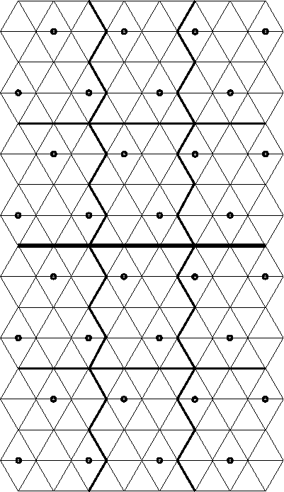

A small amount of explanation is in order for these pictures. The black-and-white one is fairly simplistic... just showing the pixels and the locations of the distance sensors. The heavy dark line running across the middle is the division between the two microcontrollers. One will be controlling the top half of components, another will be controlling the bottom half. The 2 zig-zag lines and the other 2 horizontal lines are meant to show how the LED driver boards are to be partitioned. Each board (with 4 driver chips) will cover a single region. Each of the 4 ADC's that I'm going to be using for the distance sensors will cover 2 rows of distance sensors.
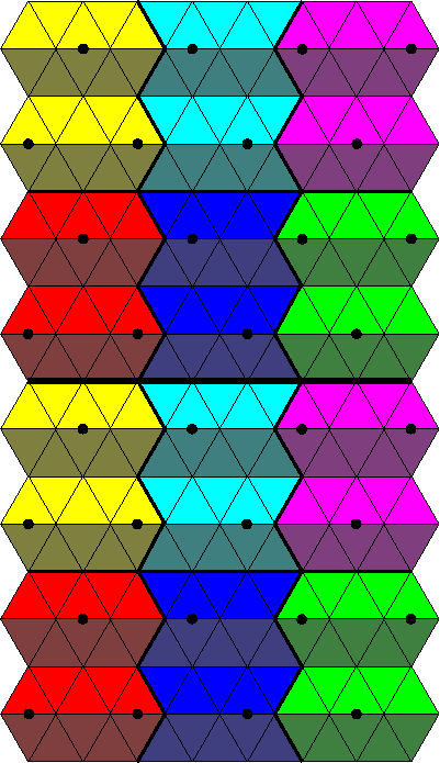
If needed (for framerate reasons), I can also split the design up into 4 microcontroller regions, so each microcontroller has 60 pixels and 8 distance sensors. This may be a better approach, because I really have no idea how much computation or communication time is going to be needed for the ADC's. Switching over from 2 to 4 microcontrollers shouldn't be too much of an issue either. The colored plan is merely to illustrate the arrangement of driver chips to LEDs that they would be controlling. A single driver chip would be controlling all same-colored, touching triangles in a given region. So all of the bright yellow triangles on the first row are controlled by 1 driver chip, all of the darker yellow ones below it are controlled by a 2nd driver chip, etc. This makes 48 driver chips in total.
Acrylic + Contact Paper
So I picked up a smallish piece of acrylic, an acrylic knife, and a hard plastic "squegee" today for testing out my diffuser idea. First, I tried cutting the 0.093"-thick acrylic with the knife. It took about 10-20 scoring attempts before I was finally able to break it. If I were to use acrylic that thickness for the final project, I'll probably do 20-40 instead. It didn't quite shear perfectly.
After that, I attempted to apply contact paper to the thin strip I snapped off. It went OK, except that a few stray random hairs and other debris managed to get between the contact paper and the acrylic. The contact paper ripped rather easily if there is something hard under it when I was trying to remove air bubbles from under it. The effects of the rip were minimal and recoverable, but certainly not desirable.
For my second attempt, I moved to a safer area and tried to keep it as clean as possible. I was working on a much larger piece, one that required 2 full widths of contact paper to cover completely, so I had a much harder time getting it on there straight. I faired much better with debris between the contact paper and the acrylic, but it still wasn't perfect.
The results were, however, vastly superior to the paper I had been using before.
Here are 2 videos of the latest incarnation of microcontroller + driver chip test board with the acrylic and contact paper diffuser:
| Dark Room (4.2MB) | Lightly Lit (3.7MB) |
| |
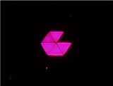
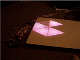
Of interest (that you can't tell at all from those videos) is that those 5 pixels are being driven by 2 driver chips. The first chip is driving the 2 pixels on the bottom (starting from the blank area) and the second chip is driving the remaining 3 pixels.
This setup is such that the contact paper is on the bottom side of the acrylic. I tried it the other way around (with the contact paper on the top surface) and it was far too fuzzy. My guess is that the light was getting diffused slightly through the acrylic and then hit the contact paper, which diffused it more, instead of the contact paper diffusing it completely and then the acrylic just transmitting the light. I'm no optics expert, but I do know what looks better.
Parts
I also got in another shipment of parts from DigiKey today. This shipment contained all the headers, sockets, and caps I'll need for the driver test boards that should be here on Wednesday. Progress marches on...
posted by Jurek @ 11:10 PM
![]()
![]()
0 Comments:
Post a Comment
Links to this post:
Create a Link
<< Home