Jurek and the Amazing Techno, Colored DreamWall

Jurek and the Amazing Techno, Colored DreamWall

The title is mostly a placeholder, as I haven't really figured out a name for it yet. This project is a wall hanging that consists of semi-large triangular pixels using discrete RGB LED's and PWM to control intensity levels of each LED, resulting in a 4096-color display.

Friday, December 28, 2007

New stuff

New Stuff!
Yesterday (the 27th), I ordered a whole bunch of stuff for work on the different projects I have.

Translucent Silicone
One of the big steps/innovations was the discovery of a little something called Translucent Silicone. This stuff is pimp, and diffuses light like nobody's business. I ordered an engineering sample from Rubber-Cal and got a smallish (2.5" diameter?) circular 1/8" thick piece. The piece itself was probably too thick for what I need, so I ordered 1/16" stuff.
The smallest piece I could order from them was 36" wide x 5' long (lengths go from 5' on up). At ~$100 for 15 sq. feet, it's not cheap, but it's great stuff. It's also flexible and slightly spongy, so it opens up many more uses than the acrylic + contact paper I have been using.

Liquid Translucent Silicone
I also ordered up a sample size of some SORTA-Clear from Reynolds Advanced Materials, which is a liquid translucent silicone, which can be painted or molded/cast into whatever shape needed. This option opens up far more possibilities than even the sheet silicone, as I can make enclosures/balls and edging to satisfy any needs. Simply by carving and dremeling/sanding some pieces of wood, I can get some very simple molds to cast any parts I would need.
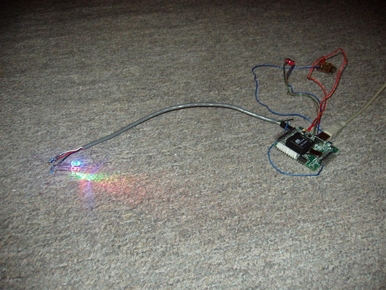
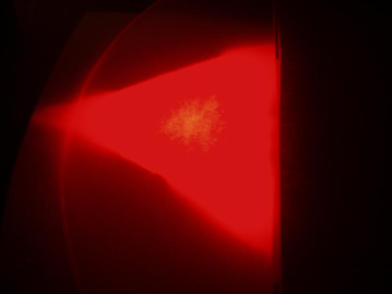
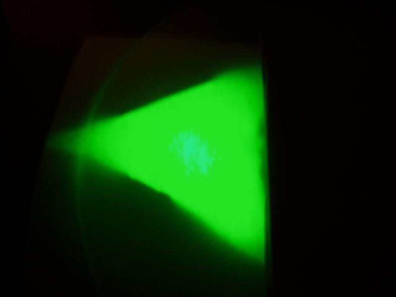
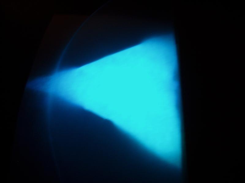
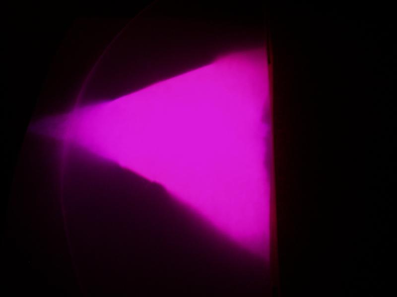
LEDs
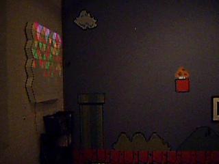
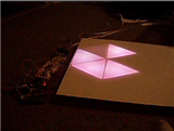
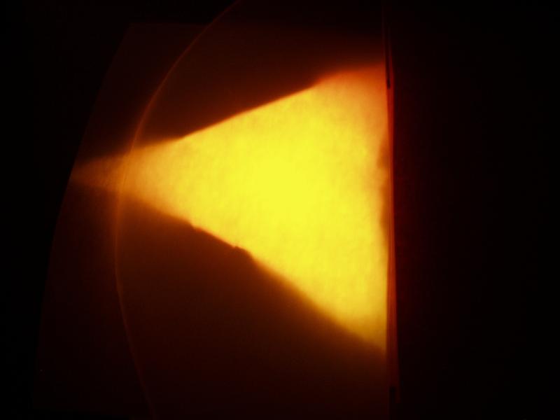
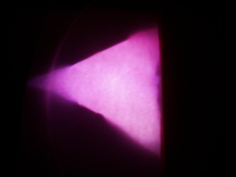
On a less-exciting, but still cool note, I finally tried out the 3-color LEDs I had gotten a long time ago from Super Bright LEDs. Their output intensity leaves something to be desired (1200, 3700, & 700 mcd for RGB, respectively), the color mixing works wonderfully. I may try using two LEDs per pixel on the cubes, and multiple ones on the sign backdrop, depending on what works.
Two should spread out the light fill much better, especially if I need to go with some pretty thick silicone to diffuse it properly.

Miscellaneous Crap
And finally, to go along with all of this, I also bought:
  • 1/4" velcro, finally
  • Scale
    • from McMaster-Carr, a great industrial supply site
    • used for measuring for the liquid silicone, as it comes in parts A & B that need to be mixed for it to react
  • Weld-On #3 acrylic cement
    • also from McMaster-Carr
    • for joining the sides of the acrylic cubes, of course
  • 16oz. mixing cups
    • disposable, for the liquid silicone, and anything else that needs them
  • More testing LEDs
    • 3500 mcd R
    • 8000 mcd G
    • 2500 mcd B
    • All for testing; I got these to align with the same candella ratios as the 3-color LEDs. If these don't work worth a damn, then I'll just go back and order a bunch more 3-color LEDs and resistors to match the currents.
Hurray for buying stuff!

I should get most of this by mid-late next week (Thursday?), but since Tuesday is a holiday and some places will be short-staffed on Monday, probably not until the following week.

Labels: ,

Friday, November 17, 2006

Show Update

Recovery
I took all of today (Thursday) off from work just so I'd have enough time to finish fixing the wall. It took me, in total, about 6 hours to completely do everything.
I tried using some superglue to fix the mashed wall section, but I doubt it did any good. The "wood product" used in this area is so porous, that the super glue just kinda soaks in and disappears. I taped it together for a while to let the glue set, and then just covered it all up with more aluminum tape. The final step was painting the outside. It took quite a bit of paint (relatively speaking), because like I said before, the wood is very porous without the hard markerboard surface, that it just soaked up much of the paint. In the end, the area was cleaned up pretty well. I felt like a plastic surgeon from the 1940's for war injuries. Just fix it up enough to function.
The acrylic was fairly easy to cut. 2 scores to get it to the "rough" rectangular shape, and then another 6 triangular wedges, with 8 scores, and the whole piece was completely cut.
The contact paper was pretty annoying, and I think it looks horrible close-up without the lights on, but you really can't see anything bad when it's 5 feet away and/or the lights are on. I didn't really have a whole lot of time to deal with trying to get it to look perfect, so I had to just leave it as it is.
I drilled 8 holes, 2 per piece of wood, for securing the mounting blocks to the wall, and used 1 1/2" #8 bolts to secure them to the wall. Hopefully, with those and the Liquid Nailz, it shouldn't come loose again.
The velcro took the bear's share of the time, at probably about 4-4.5 hours. It's a very tedious operation. Oh well, such is the way of things.
I then used 1" screws (instead of 3/4") to secure the mounting hardware to the wall, so that it actually goes into both pieces of wood.

After making all of the updates, I made the tricky decision of hanging it back up where it was before. I would be very, very surprised if the mounting brackets gave way again.

I took a small video of the wall in its mounting place for the art show. Here ya be (2.24MB QuickTime):


At this point, about all I can do is hope for the best. I will be at the opening tomorrow from maybe 6:30 or so until who knows how late.

That is all, signing off.

Labels: ,

Thursday, October 12, 2006

Gluing progress

Assembly
20 more pixels glued into place. That leaves me 33% done with the gluing. This round went much faster than the first time. Woo!

Coding
I've just been playing around a little bit with things here and there. Currently, there's not a whole lot I've been really attempting. I would like to have some sort of unique pseudo-random number generator. Pseudo-random is fine for what I need, but that's only as random as its initial seed, which is deterministic for the microprocessor without any sort of analog input (white noise, ADC, user input, etc). I think the easiest approach currently would be to have a small switch on one of the unused ports that can be pressed at any time while it's running that would update the seed. I could just have an unsigned int as a counter for the main loop, and whenever it detects the switch as closed, I can just call srand with the counter as an argument.

Parts
I'm going to be ordering a few odds and ends (wire, terminal blocks, crimp terminals) for the current stages I'm in.
I've recalculated a few times how many of each length of LED triplets I will need, and with my current calculations, I need to solder 31 more triplets of various lengths (2 10", 17 8", & 12 4") for the first module.

Labels: , ,

Monday, September 04, 2006

Finally Moved In

So I've finally gotten moved in (2 weeks ago, even) and mostly have my workbench set up again. It's a slightly slow process, as anyone who has moved many times can attest to.

Acrylic
Before I moved, I managed to get one (of two, per module) of the 0.093" pieces of acrylic cut. It went fairly easily, which I was glad for, and it looks pretty good. I'm still trying to figure out how it will attach to the wall. I don't really want to glue it on, sealing all of the pixels, and I can't have any nasty hinges on the sides. My current thinking is to have long, thin bolts that go all the way through the wall floor. They will need to be 2.25-2.5" bolts to be able to do this. Any ideas are certainly welcome.

Alumin(i)um Foil
I decided to buy some aluminum tape instead of trying to wrangle with aluminum foil. The stuff I found fits perfectly. It's 2" tall and is the exact height of the inside of the pixel walls. I tested putting pieces on one of the pixels and it went together very easily. I used 2 wooden dowels/chopsticks to help position and place the tape and get it affixed in the corners. My fingers are far too fat to get into the corners of those 60 degree angles (not that I have fat fingers). I am quite happy with the results.

LEDs
I still have yet to find/buy a hot glue gun. I know fabric & craft stores have them, but I just haven't gotten over to one to pick up a gun yet. I don't know why I didn't think of hot glue before; screw epoxy, super glue, and caulk.

Hopefully this week, I will start working on stuff for real again. It's been far too long :|

Labels: ,

Sunday, June 11, 2006

More soldering and gluing

Soldering
12 more (2") LED triplets soldered. 88 done, 152 to go. The 2" sections were kinda tricky, because the wire length was so small and the heatshrink tubing needed to be a certian length just to go over everthing properly. I ended up having to rearrange a few steps in the process to get everything assembled correctly.


Gluing (a.k.a. Construction)
I cut and glued 4 more pieces to the outside of the 1st module. They were all 3"x5.5" pieces. That leaves another 10 pieces on the outside zig-zag part left to cut and apply. For this module, I also need to make room for the battery pack, so I have to extend the bottom side pieces an extra bit, plus have a second long piece on the bottom. The exact dimensions are yet to be determined (I haven't been ambitious enough to sit down and do the measurements). It involves angles and what-not so it's not entirely nontrivial (yay double negatives! Me fail english? That's unpossible!).

Parts
I also ordered 170 2x2 connector housings (sockets) and 500 crimp connectors. The connectors weighed in at a whopping $1.28 each, so the total order ended up being over $250 for just those items (the crimp connectors are very cheap).

This last Digikey order put me near $5k ($4.8k). Lots more to come in that department though. Yet another milestone, I guess. Or something.
*watches as his wallet bleeds more*

Labels: , ,

Thursday, June 01, 2006

Construction and Parts

Construction
Over Memorial Day weekend, I got some decent progress made on the construction. I got one of the long 3" external pieces cut and managed to attach it and two of the shorter pieces to the wall. These pieces are 1/8" marker board, so when two modules are abutted, the common pixel separation will be 1/4", which is what the inter-pixel divisions are in a single module.
I used Liquid Nailz to attach them to the wall, as 1/4" is far too thin to attach anything using nails or screws and I'm not sure how the marker board would hold up to a lot of drilling and pounding. It's holding up well so far, as I've used the Liquid Nailz as basically cement, and I went back in and filled in all the joints with even more.

I also drilled and slotted the remaining 60 holes needed for the LED cables. This went really quick, because I could use the previous 60 holes as a guide.

Parts
With all this progress comes even more parts ordering. I ran out of 1/8" heatshrink tubing, so I bought another 60' of that, as well as some caulk, more Liquid Nailz (used above), and some clear Liquid Nailz, in case the clear caulk doesn't work too well in attaching the LEDs to the wall. I also ordered and, today, received 525 more LEDs from SuperBrightLEDs. I ordered 175 of each color, along with the 90 I already have (about 10 were used as "engineering samples"), should leave me with enough to complete the project and a few left over in case I screw something up.

I will need to order some more 2x2 socket headers and some more 4-conductor wire soon as well, as I am quite short on what I need.

Labels: ,

Saturday, May 13, 2006

Slow progress

Sorry for no updates in a while. I was out of town for work for a week and had a few other things going on the following week.

I've got the next batch of 17 LED triplets done, so now I'm up to 64 of 240 done (past the 1/4 mark!).
I bought another 300 feet of 2-conductor wire and another 70 feet of heatshrink tubing (all for a whopping $30! Gotta love Axe-Man). This should keep me going for a little while anyway. I will need to order some more LEDs soon, as well as some more 2x2-pin headers that connect to the driver boards.

Whee!

Labels: ,

Friday, March 17, 2006

Changes, Progress Reversal, and Updates

Changes & Progress Reversal
OK, so I think I've completely decided on switching over to the new construction method. It will afford me many more benefits than my current construction. I will only be losing about 20 hours or so of work and about $100 worth in lumber that can't be used any more.

The new method is similar to what other people have been doing, and I don't know why I never thought of it before. The only major difference is that I need to intersect 3 pieces of wood, instead of their two (triangles, instead of squares).
For reference, see this post and this image:


The big split between halves half-way down will still be there, but everything else will be changing. My plan is to have the pixel walls be about 2" tall (I could maybe go smaller too) and be about 1/2" thick plywood. I would use 1/4" plywood, but I need to have the outer walls be 1/2 the thickness of the inner walls. This way, I can abut any two wall sections seamlessly.
Every 5.5" (the pixel length), there will be one or two slits, depending on which axis the wood piece is, that extend a full 2/3 of the height of the wood, leaving only 1/3 (~0.66") of the wood remaining for structural integrity. The three axes of wood lengths will then be slotted and glued together (I shouldn't need anything more than glue for them; they're strong even without glue). This will give me a pseudo-honeycomb (except triangles instead of hexagons).
Then I can just affix a piece of plywood to the bottom (the thinner, the better) and I basically have the entire enclosure (minus the acrylic top, of course). On the outer walls, I was planning on using 1/4"-thick plywood, like I said, but it would be 3" tall, instead of 2". This would give me a subfloor with which I can mount the electronics and run the wiring. Since I won't be having any border around the wall, I need everything completely self-contained.

Well, almost completely. There's still the issue of the power supply. It's a full 2"x3.75"x5.8". Which means that I could mount it in an enclosure that hangs down an extra ~4" on the bottom of the bottom wall "module".

I should be able to have all of the connectors between the bottom and top modules (USB, power, SPI, and switches), as well as connectors for modules to the left and right of each of them, flush with the edge of the wall. The 1" margin on the bottom will be enough for this.


Updates
I spent a whopping $18 on 70 feet of heat shrink tubing and 100' of 2-conductor 26ga. wire at Ax-Man today. I figured I should spend as little as possible for just testing. I got maily 1/8" tubing, with some 3/16" as well. The 1/8" is a little too big for what I need and it was as small as they had, so if I were to get more, I would get 1/16" or 3/32", depending on what suppliers had available. The wire worked decently and I finally figured out a way to solder the wires to the resistors and LEDs. The only problem is that it took a moderate amount of time, so I have a long way to go. I now have one LED triplet done (yay 0.4% completed!) and I've verified that it works. It's just over 19" long, so it should be long enough to go from the board to the furthest-away pixel. That's one nice thing about having separate driver boards; I can have the boards centered around the pixels they're powering and not have to deal with LED wiring that're several feet long.

Tomorrow, I must go buy lots of wood and start cutting. I will have to come up with a way to make 4'-long cuts in plywood with a jigsaw go fast and straight. I have 54 2"-tall pieces to cut and 36 3"-tall pieces to cut. Fun, fun!

Labels: ,

Monday, March 06, 2006

The Good, the Bad, & the Better

Wow... what a week.

The Bad
On Sunday (the day after my previous post), I decided to pull out the microcontroller board and test out the processor. I also had plans on trying out the processors I bought for this purpose, so I didn't have to use the one that came with the starter kit as well as plans to test my newly-finished uC board.

I pull out the board, dust it off, put the processor in, and hook it up. Nothin'. Windows says it doesn't know what the hardware is and that I should unplug it and plug it back in. !*@* I play around with things for a while: I try reinstalling the software; I try a different uC; I try using a different computer. Still nothing. Ugh...

I check DigiKey to order another one. They have 1 (!!!!!) in stock, and it's for $82 instead of their normal $132. At least something's looking up. I also need to order a bunch of resistors, as I finally found a good match for mixing. 280 Ohms for red, and 69.8 Ohms for both green and blue. These values are driving red at 10mA and both green and blue at 20mA. Go figure, the red at the same mcd power is twice as powerful as green or blue. Oh well...
So I add 500 69.8 Ohm resistors and 250 280 Ohm resistors to my shopping cart (240 pixels) and I add in a few random switches to test out for the reset button, voltage source, USB unload switch, and ISP switch and off my order goes... ZOOM!!! I love 2-day ground shipping for $5.

The Good
So then Tuesday rolls around and I get my uC starter kit board #2, 750 resistors, and switches. I didn't have any time to play around with them at all Tuesday or Wednesday, so they sat awaiting my involvement until Thursday. Thursday rolls around and I pull the new starter kit out and hook it up. Wonderfully (and expectedly), it works on the first try.

OK... now what?

I take the new processor out of the new starter kit and stick it in the old starter kit. It works perfectly...
I take the old processor and put it in the new starter kit. It works perfectly...
I take the old processor and put it in the old starter kit. IT works perfectly...

AUGH!!!!!!!!!!

So my stupid self actually had the processor in wrong. I had it rotated 90 degrees and had just assumed that the package of the processor or the socket wouldn't allow me to do that. Oh well... not all is lost.
What this allows me to do now is to use the SPI (Serial Peripheral Interface) (or even the TWI for that matter) to do inter-uC communication testing. Whee, what fun! I played around a little bit and (thought I) managed to get the two processors to communicate properly. Oh what joy abounds!... almost. It turns out that that wasn't the case at all.

I had also ordered through Techni-Tool a bunch of different supplies, including a new circuitboard vise, solder reel, tip tinner, and (most-importantly) a smoke absorber. They are scheduled to arrive on Tuesday, so I can continue my soldering fun then!

The Better
OK, so Saturday, I dive back into the board and try to do more with the inter-uC communication. I turned the slave board on and noticed that the light patterns were exactly the same as I was seeing before, except this time it wasn't hooked up to the master board.
After some debugging, I found out that there is a pin on the SPI wire set (there are 6 on the starter board) that is called SS. This stands for Slave Select and is only supposed to be asserted if it is supposed to be the slave that is being communicated to. I had these hooked up to each other, so I'm sure they were just freaking out about who was the slave. Anyway, Atmel had some sample code that didn't use the SS line, so I just used that instead.

Two starter kit boards, hooked together via SPI. Note that the slave board isn't being connected via USB to anything; it's getting its power from the SPI bus.


Lit version:


Quicktime Movie (2.33MB):


I got a pretty non-random pattern to successfully be transferred from the master to the slave uC and it appears to work properly this time.


I also got a wild idea to test my as-of-yet untested uC board that I finished soldering a couple weeks ago. I reprogrammed the uC to just randomly blink the LEDs on the test board (which use Port 3 of the uC) and then dropped the uC into the test board. What followed made me very joyous and I breathed a very big sigh of relief. What this amounts to is that the board had been started 7 months ago, involved many different steps and revisions, caused me many headaches, and kept me up at night wondering if the core component would actually work. Huzzah! (No one says "Huzzah!"... sheesh...)

Picture of the setup:


Quicktime movie of the lights a-blinkin' (1.05MB):


The Caveats (special feature!):
  • For some reason, the voltage regulator is outputting at 4V instead of 3.3V, but the chips I use support up to 5.5V, so that's no biggie.
  • I haven't tested either of the ADCs on the board
  • I also haven't tested the USB data port (the computer never recognized the device when I plugged it in, so I'm sorta suspect about that)
  • Nor have I done an exhaustive test on the ports (only a few pins of Port 3)
  • I also haven't tested the current limiter on the USB port, so that may or may not work either. It wouldn't be the end of the world if that didn't work, however.
  • I still have to figure out how to solder the LEDs together on a piece of wire. The one piece I soldered together looks like crap and won't work at all. Plus, I have to do 240 of them. Fun, fun!

Labels: ,

Saturday, February 25, 2006

Pixel row test setup

Over the last week (and mainly just today), I've been trying out some methods of creating the internal divisions between the pixels in a given row. I already built a single 15-pixel row earlier to start things off, so I've been using that as my test vehicle.

I bought some flashing from Home Depot to do the separators (as I stated in the previous post) and cut a 2' strip. I then cut it in thirds lengthwise, giving me 3 pieces 2' by slightly less than 2".
I screwed up the first piece pretty early, as expected, and then actually thought ahead about how to cut the 2nd strip before actually cutting it.
The second strip worked out well, except I couldn't measure correctly and ended up with a zig-zag piece in which every straight length was 1/4" too short. I also had a hard time actually attaching the metal to the plywood. The nails (carpet tacks, actually) I bought are absolutely tiny and the only way I could pound them in is by using a needlenose pliars to hold them. The hammer head barely fit into the box and I kept hitting the flashing with it too. And on top of all of that, the plywood just absorbed all of the force of the hammer because it was being suspended by the walls.
The 3rd strip actually worked out well. The 2' piece I had cut ended up being about 2" too short for what I needed, but that was fine as I really didn't need to test a whole 5 pixels or anything. I used a 1/16" drill bit and pre-drilled into the flashing and a small amount into the plywood to use as a pilot hole. Then I used a (very) small amount of wood glue on each carpet tack and just pushed it in with a pliars instead of with the hammer. This worked considerably better than my first approach. I need to pick up a punch though, because the pliars can only push so hard and I need to get the nail/tack more flush than it currently is.

I just used my LED tester to wire up RGB LED's, mainly because it was a lot easier than any other method. The red was overpowering the green and blue so much (with all 3 at 10mA) that I dropped the red down to 5mA. This worked out surprisingly well.

I also experimented with the 1" border between each of the pixels, just to make sure that everything still jibed with my earlier design work. I used black duct tape (I couldn't find my electrical tape) and lined everything up properly. I think it looks pretty decent.

Here are some pictures of the whole thing:
Test pixel row, with 1 pixel lit up white:


The guts of the row, with the pixel on still:


3 of the pixels, close up, with carpet tacks visible:


Pixel mask with 1" borders (the only border that is 1" is the common section between the two; Using an incandescent lightbulb for backlighting):

Labels: ,

Monday, February 20, 2006

Miscellaneous updates

Bookkeeping
I've added a bookkeeping .xml file to the site, so everyone can see exactly how much money I've wasted on this glorious hobby. It is under the links section.

"Other"
I bought some flashing today and a metal scissors to cut it with. I have yet to test it out; I will be doing that shortly. The idea is to use the flasing as a barrier between the 15 pixels (or 30 in the double row) of a row. Then in order to compensate for the pixel wall thickness differences, I plan on painting/coloring/etc the inside of the acrylic to be the correct width. This will also give me a little bit of slop for positioning the flashing, as I don't need it to be exactly on the pixel line.

Yay progress!

Labels: ,

Thursday, August 04, 2005

Progress and Setbacks

Yay for finally getting some more work done.

Microcontroller Board
I started off on Monday by baking (with my wonderful new toaster oven) one of the boards and ~8 components. I baked them for 7 hours at 150F on Monday, ~1-2 hours on Tuesday, and 5 more hours on Wednesday. After Wednesday's baking session, I pulled them out of the oven and set out to soldering the components to the board. All the components were for the voltage regulator portion of the board and could be easily tested once they were soldered in place.

The first thing I noticed was that I hadn't planned on knowing what orientation the diodes and polarized capacitors needed to be in. A little bit of checking of my schematics and a quick refresher course on what pin was referred to by the small band on the diodes (band = cathode), I was able to orient the diodes properly.

The next thing I noticed was that the diodes were huge compared to the pads they were supposed to be soldered to. Like, I couldn't see either pad when the diode was placed symmetrically on them. Luckily, with some flux on the diode contacts and a bunch of solder, I was able to flow enough solder under the contacts to solder them to their respective pads. For rev 4b (if needed), I will be enlarging the diode pads considerably.

After that, the soldering was pretty much smooth sailing. I grabbed my small 4.5V 3-AA voltage source for a quick test, hooked it up with a switch (so I don't bounce the hell out of the voltage source by trying to connect a wire directly to the board), and turned it on. I had my voltmeter hooked up to the ground and voltage out of the regulator and it started freaking out claiming that the voltage across the pins was well over 1000V (NOT possible), so I unhooked everything just in case. After smelling for burnt components, I hooked it all back up, threw the switch, and then put the voltmeter across the same contact points. This time, I got a wonderful 3.496V output on the voltmeter. Huzzah! It's slightly larger than the 3.3V I wanted, but oh well. I really don't think any of the components will freak out about it.

After this initial success, I decided to solder a few more testable components to the board. I grabbed one decoupling cap, a resistor, and a surface-mount LED (for power status) and soldered them all in place. I also noticed that one of my previously-soldered caps was basically shattered on one of the leads, so I had to scrape it off and re-solder a replacement. I'm gonna end up burning through a lot more 0.1uF caps than I had anticipated. They're so large and so brittle; the ceramic cracks off very easily. Anyway, I fired it all back up again and got a wonderful amber glow out of the LED, so yet more success.

Distance Sensors
And now, the setbacks. Before, I was looking at ordering up a few more distance sensors to use and checked DigiKey for price and availability.
For part number 425-1161-ND, I saw this:

Quantity Available 0

Price Break
Call

Bad News Bears. Ruh Roh Rorge!

I have yet to call them (I will when I am ready to order some more stuff... it may be a while). I checked the manufacturer's website (Sharp Microelectronics) and found that there are 2 other resellers of the part (Future Electronics and Jaco Electronics).
Future has them in stock, but they only sell in quantities of 100. At $8.625 each, that would lead to quite a hefty investment; one I'm not willing to take at this time.
Jaco has it listed as 400 in stock, but they don't have any online ordering mechanism. They have a Minnesota contact number, so I might call it to find out, but my guess is that they only deal in 100-count quantities as well.
DigiKey has the 4-30cm (~1.5"-~11.8") version available and is the same price, but I don't really want that range. That's getting too close to the wall itself. I also found that they had an unlisted version (425-2046-ND) that appears to be approximately the same thing (it's also analog with 10-80cm of resolution), but the availability for 25 of them is Nov 1st. Ye-ouch... not cool.

So I may not be using the distance sensors at all. Harumph is what I say to that. We'll see, but the prospects are not that great.

Labels: ,

Thursday, July 28, 2005

Pre-vacation Status Update

So I got the controller boards as expected, but I then started gathering parts for the voltage regulator (because that's the first section of the board I plan on soldering and testing) and I realized that I was missing a certain diode I need for it. After some searching around of order forms from DigiKey, I noticed that I never ordered any in all of my many orders (7+ now). So there was no way for me to solder or test anything on the board (or anything that I wanted to solder or test, that is).

I ordered and received 300 (100 each) red, green, and blue LEDs as well. When I received those, I then decided that I needed resistors to match the intensity values, so that gave me an excuse to get the diodes I need for the voltage regulator. I ordered those up the following day and got it all in. I spent some time last night testing relative intensity levels and trying to mix a good white out of the 3 colors. My initial calculations put the resistances I needed for red, green, and blue at 133, 62, and 66 ohms, respectively. So far, after getting very close, I have ended up using about 280, 30, and 70 ohms, respectively. For some reason, the green is VERY weak, and the red is way overpowering (I mostly assumed this was going to be the case for red).

I also picked up a toaster oven so I can bake the boards and components before and after I solder them. The reason for baking them is to remove any moisture that is on them so they don't explode while soldering them (I'm not super worried about this, really). After I'm done soldering the boards, I will also be cleaning them with hot, soapy water and then isopropyl alcohol, to remove any flux left over on them. Should be good times.

Anyway, no updates until at least Monday as I am off to wonderful Las Vegas for the weekend

Labels:

Monday, July 18, 2005

Ahem.....

Wow... 9 days without a post...

Just a quick status update here... it's full-blown summer now and there're a lot of activities floating around to take time away from this project.

I ordered 10 controller boards from ExpressPCB last week. They should be here tomorrow. Then the fun begins again.

I bought a bunch more wood from Home Depot. I also picked up a bunch of bolts and angle brackets to try to join the boards together. We'll see how that all works out. I'm hopeful, but not much more than that.

I also made another DigiKey order today. I just ordered a bunch of headers for the sockets, an adapter for the power supply and fuses so I don't blow stuff up, a couple ADCs, some random resistors and capacitors, and a few surface mount LEDs for the controller boards.

I'll keep status updates going when I feel there's enough to report on.

Labels:

Monday, June 20, 2005

More parts

Not any big updates yet... My whole weekend was busy with another task and I had no time to do any real work on this project.

I ordered 60 LED driver boards with a modified layout from the original one. I had to enlarge all of the header vias. I also grew the board by 0.1" on each side (to 1.9" square) and moved stuff around a bit to adjust for this. "rev 3b" of the board should be here by about Friday or possibly Monday.

I also ordered a bunch of other stuff from DigiKey today. It was mainly just components for soldering the driver boards, but I also ordered the power supply I had picked out.
It's a power supply that outputs 5.1V and up to 13.6A (normal convection cooling) or 19A with forced-air cooling. If all 15*16*3 (720) LED's are on at 20mA each, that means that the wall will draw at-most 14.4A. I will probably mount a small (10mm or so) fan to blow across the power supply just in case.

Labels:

Monday, June 13, 2005

Acrylic + Contact Paper = Super-Happy Fun Time

So I was informed (and it makes sense) that most people really don't have any idea what the wall will actually look like. I've talked a lot about it, but never really had any visual aide to go along with it. Well, here you go:


A small amount of explanation is in order for these pictures. The black-and-white one is fairly simplistic... just showing the pixels and the locations of the distance sensors. The heavy dark line running across the middle is the division between the two microcontrollers. One will be controlling the top half of components, another will be controlling the bottom half. The 2 zig-zag lines and the other 2 horizontal lines are meant to show how the LED driver boards are to be partitioned. Each board (with 4 driver chips) will cover a single region. Each of the 4 ADC's that I'm going to be using for the distance sensors will cover 2 rows of distance sensors.

If needed (for framerate reasons), I can also split the design up into 4 microcontroller regions, so each microcontroller has 60 pixels and 8 distance sensors. This may be a better approach, because I really have no idea how much computation or communication time is going to be needed for the ADC's. Switching over from 2 to 4 microcontrollers shouldn't be too much of an issue either. The colored plan is merely to illustrate the arrangement of driver chips to LEDs that they would be controlling. A single driver chip would be controlling all same-colored, touching triangles in a given region. So all of the bright yellow triangles on the first row are controlled by 1 driver chip, all of the darker yellow ones below it are controlled by a 2nd driver chip, etc. This makes 48 driver chips in total.


Acrylic + Contact Paper

So I picked up a smallish piece of acrylic, an acrylic knife, and a hard plastic "squegee" today for testing out my diffuser idea. First, I tried cutting the 0.093"-thick acrylic with the knife. It took about 10-20 scoring attempts before I was finally able to break it. If I were to use acrylic that thickness for the final project, I'll probably do 20-40 instead. It didn't quite shear perfectly.
After that, I attempted to apply contact paper to the thin strip I snapped off. It went OK, except that a few stray random hairs and other debris managed to get between the contact paper and the acrylic. The contact paper ripped rather easily if there is something hard under it when I was trying to remove air bubbles from under it. The effects of the rip were minimal and recoverable, but certainly not desirable.

For my second attempt, I moved to a safer area and tried to keep it as clean as possible. I was working on a much larger piece, one that required 2 full widths of contact paper to cover completely, so I had a much harder time getting it on there straight. I faired much better with debris between the contact paper and the acrylic, but it still wasn't perfect.

The results were, however, vastly superior to the paper I had been using before.
Here are 2 videos of the latest incarnation of microcontroller + driver chip test board with the acrylic and contact paper diffuser:

Dark Room (4.2MB)
Lightly Lit (3.7MB)


Of interest (that you can't tell at all from those videos) is that those 5 pixels are being driven by 2 driver chips. The first chip is driving the 2 pixels on the bottom (starting from the blank area) and the second chip is driving the remaining 3 pixels.
This setup is such that the contact paper is on the bottom side of the acrylic. I tried it the other way around (with the contact paper on the top surface) and it was far too fuzzy. My guess is that the light was getting diffused slightly through the acrylic and then hit the contact paper, which diffused it more, instead of the contact paper diffusing it completely and then the acrylic just transmitting the light. I'm no optics expert, but I do know what looks better.


Parts

I also got in another shipment of parts from DigiKey today. This shipment contained all the headers, sockets, and caps I'll need for the driver test boards that should be here on Wednesday. Progress marches on...

Labels: ,

Sunday, June 12, 2005

Driver board and parts

OK, it's been over a week since my last post again. My posts will probably be only 2-3 per week (or less, depending on how things go). It's summer and my desire to sit inside has waned slightly.

Driver Board Design

Last Friday/Saturday, I set out to design a board with 1 driver chip per board. This was fairly trivial, because it was just a single 24-pin chip, 2 resistors, 1 capacitor, and a bunch of headers (for input signals, LED power, and LED wires). The limiting factor on how small I was able to make it was the headers along the outside edge of the board. The final board for that design was 1.1" x 1.3".
Sunday/Monday, I decided to put 2 driver chips on a board. When I had computed the cost for ExpressPCB's "Production" service, they had a minimum area per board (for cost reasons) at 4 square inches, so if I ordered 48 driver boards, the per-area cost was very high. Also, I had a ton of dead space on the back side of the board (I basically didn't use it at all) and I could easily put the 2nd chip on the bottom of it without too much issue. The final size of that board was 1.2" x 1.3". I had expected it to grow a bit more than that, especially since I had switched to headers that were 2 rows instead of just 1.
Since the 2-board area was still well under 4 square inches, I decided to try to see how a 4-chip board would be. Man, oh, man was that rough to route. I placed the chips and optimized the routing so that the LED signal pins were the shortest and easiest to deal with, mainly because there are 60 on the board. What that left me was 4 chips (2 on each side of the board) basically in opposite corners all pointing at each other. While not extremely hard in itself, there are 3 common signal pins, power, ground, and a unique signal pin per chip that needed to be routed. And they all need to cross each other in the center of the board. Oh yeah, and I had to design the LED voltage source to be able to handle at least 1.2 amps (20mA per LED * 60 LEDs) so the traces needed to be pretty wide.

Here is the end result of 2-4 days of layout and tinkering:

Top + SilkscreenBottomTop + Bottom


This board is 1.8" x 1.8" (which is over double the area of the 2-driver board, but this one was designed better with ground plane in mind. All of the shaded areas on those images are part of the ground plane. The thick traces running along the bottom edge of the board are able to hold at least 1A (and there's complementary traces on the top and bottom sides of the board to help distribute the power).
I ordered up 2 boards with just the "Standard" service (It doesn't have the silkscreen layer--the yellow outline in the first picture, nor does it have a solder mask--any non-via and non-contact areas are coated so the metal can't be soldered) to see how things work with it.

I also ordered a bunch of headers for the boards and a 12-bit, 8-channel ADC from DigiKey. The ADC has almost the same pin pitch as the driver chips (the ADC has a pitch of 0.65mm, which is 25.6mils) and has 16 pins, so that should be "fun" to test. With 14 distance sensors per half of the wall, that means I need 2 of those chips per half. I still really don't know how I'm going to test them, since their package is so small and I don't want to order up another batch of DIP adapter sockets. I will probably just design the board for them and see how it goes. The only major issue is that each chip is $8.10. Granted, I only need 4 of them, but if anything goes wrong, then that's potentially $16 I've wasted on lazyness.

Wall Construction Design

Since I had no suggestions about other materials to use for the pixel walls, I had to start hitting up people about any ideas they might have. One of my coworkers had a great idea of using tin to separate the pixel walls. It's light, opaque, relatively-easy to work with, and cheap. Since I need to be able to mount the distance sensors in every-other row, I need those rows to still be wood, but the off rows can be tin dividers. Also, each row's pixel divisions can be all tin as well. The outside walls will still need to be wood, as will the floor of the pixels (which will be about an inch down from the top).
To counter the fact that some rows will have a wide piece of wood and others will have a very thin piece of tin, I think the best approach is just to paint the underside of the acrylic black to make a uniform pixel boundary. I should be able to get straight-enough lines by using masking tape and then using some sort of black paint (I'm not sure which will stick to acrylic best yet... I'll take any suggestions/comments on it).

I also came up with a great idea for a different diffuser. I had some contact paper just lying around and decided one day as I was walking out the door to go to work to see how well it would work. I grabbed a roll, peeled off enough backing to stick it over a pixel, and turned the pixel on. It was amazing! Completely solid color with no "pulpy-ness" to the diffusivity. I actually kill 2 birds with 1 stone with this too. Not only does it diffuse amazingly well, it's also its own adhesive to the acrylic. I just have to stick it on and that's it. That's not to say that getting contact paper to stick to a large area without any creases or air bubbles is easy, but it would certainly be easier (and look better) than using a bunch of sheets of paper.


Once I get these test driver boards in and wire up more than 5 pixels, I will get some more cool-looking videos for everyone. (They better be cool-looking).

Labels: ,

Monday, May 16, 2005

Color mixing

I put in another order with Digi-Key today. This order consists of the correct sizes of resistors and capacitors (hopefully). I also ordered a couple PLCC sockets for the uC as well as 3 uC's (just in case) and some other random sockets and headers I may or may not need.

My order of test LEDs from SuperBrightLEDs came in today.
I was hopefuly of the 3-color LEDs, but it turns out that the colors come out parallel, so that there's a small amount of overlap of colors, but the cones are all in a line and would never mix properly. Oh well, that's what testing is all about.
I also got 3 bright individual colors and used those to test instead. I had never really had a good setup to test mixing of colors; it was always just me trying to hold 3 different LEDs at 120-degree angles and all focused at the same point on a piece of paper while looking through the acrylic from the other side. Basically, a real hack job.
I grabbed some cardboard from a shipping box and cut out a square and then used a triangle pattern to form a triangle box to mount the LEDs. I lined this little box with aluminum foil and then taped a white paper triangle in the center. I cut slits in the middle of each of the walls, to hold the LEDs and... viola... this is what resulted:

Not especially snazzy, but hell, it works. Here's a bunch of pictures from the results of my test:


The white is kinda weak in the green and a little heavy in the red, but I think I can play around with that fairly easily. The top diffuser I used was just a white sheet of paper between the triangle box and the acrylic, so it's rather chunky and not really what I'm looking for in a diffuser.

Labels: ,

Friday, May 13, 2005

Quick parts update

OK, quick update.
  • Yesterday, I received the 40 driver chips from Maxim and the 3 back-ordered LEDs from Hosfelt (they shipped those 3 LEDs in a giant FedEx box...). I haven't done anything with them yet. Probably this weekend I will though.
  • I ordered 10 each of 3 different LED colors from SuperBrightLEDs as well as 10 3-color LEDs (they were actually decently priced). I've got more testing for those to try to get the colors to mix properly.
  • I also ordered a bunch of soldering supplies from Mouser. A different soldering iron tip (hopefully, it will fit in my exisiting iron), some 15 mil solder, solder wick, a flux pen, & cleaning alcohol.

Labels:

Wednesday, May 11, 2005

prototyping & more testing

LEDs:

  • I tried figuring out how to diffuse the LED light more. A friend sent me this link about a guy who made a color-changing tap light using 2 of each of red, green, & blue LEDs by reflecting them off a white surface first. He had a link in there to SuperBrightLEDs for getting ahold of several-thousand millicandella LEDs. From the pictures, it looks like just normal paper, but I tried that with very poor results. He said it was glossy, so perhaps, it's a piece of plastic or high-quality photo paper. I still haven't properly matched light intensities across the 3 colors, so that's part of my problem as well. I'll have to keep trying things I guess

TWI Communication:

  • On Monday night, I tried to get the TWI (I2C) communication working between the microcontroller and the LED driver chip. It was a rather hacked-up job because I taped (yes, literally taped with scotch tape) the LED driver chip to a QSOP-DIP adapter chip that was then plugged into a prototyping breadboard. In addition to the standard wiring from the uC board, I also wired in 3 LED's just to test with. I grabbed the sample TWI code from Atmel's website (which puts the uC into master transmission mode, the mode I need to use) and changed a few minor things (device address and data payload) to try to get it to run.

  • I plug everything in and get nothing... nada... great! Debug time! I remembered that the normal operation for the driver chip requires 2 bytes of data (address and value) to work properly, so I change the code to write out 2 bytes before closing the connection and try again. Same thing...

  • I've got 6 LED's on the uC board at my disposal, so I use them for status indicators. I also double-check all the wiring, because it's an easy mistake and I've done it many, many times before. I also check the continuity between the driver chip and the board, since it's just taped to the adapter chip. Everything seems to be in order...

  • ...

  • ...

  • Several hours later and several frustration levels higher, about all I'd been able to figure out is that I'm not getting an ACK signal back from the driver chip (actually, I'm getting a NotACK signal back, but I think that's what would happen if there was nothing on the TWI bus). All the wiring seemed to be correct and I'm pretty sure I got the address of the chip correct. Perhaps I'll have to try a dab of glue or something else on the driver chip to get it to hold to the adapter better. I ordered 40 driver chips from Maxim's website last week, but haven't heard anything from them other than the withdrawl of funds from my credit card, so I've only got the 2 engineering samples to test with. I've also got no other devices around that support TWI communication. Back to testing, I guess!

Labels: , ,

Friday, May 06, 2005

parts have arrived!

So I got both the Hosfelt and Digi-Key shipments in today. I went through and checked stuff out. There're a few things that I probably really didn't need to get, like a DIP pin aligner and a breadboarding circuitboard, but whatever...
The magnifying binoculars are pretty sweet, but I think I'm going to get a headache pretty quickly while using them. There're 3 sets of lenses that can be put in place (1 stationary, 1 that flips down from the inside, and 1 that's a single-eye piece that rotates in from the outside for the right eye) that, when all 3 are in use, do 4.8X magnification. Really intense.
I also realized that all of the capacitors and resistors were 2 or more sizes too small compared to what I need. I'll need to order a new batch of all of them. Oh well. I missed a few other things in the order and they aren't super-critical, because I can still test without them. Everything else seems to be in order and I haven't really had a whole lot of time to check stuff out yet.

Labels:

Thursday, May 05, 2005

parts and musings

I finally got a response from Hosfelt Electronics. I think they may have felt a little bad about taking so long. They shipped it yesterday (5/4) and it's scheduled to come tomorrow, so that's better. Yesterday, I also ordered 40 of the LED driver chips as well as a shit-ton of random stuff from Digi-Key. I knew I would need a lot of stuff from there and I already had a pretty big list of stuff picked out, so I ordered lots of surface-mount discrete components (resistors, caps, diodes, current limiter chip, voltage regulator), a few headers and connectors I figured I'd probably use, a bunch of tools for various tasks (tweezers, PCB vice, crimper, scalpel, breadboard, etc), and 2 sensors. I've been kicking around ideas about what else to do besides just lights. I can't really do touch sensors on a wall piece, so I started thumbing my way through the catalogue and came upon quite a variety of sensors. Two that struck my eye were a surface-mount illuminance photo-IC sensor and a distance measuring sensor. So I picked up one of each to give them a try.
The illuminance sensor measures about 1 to 3000 Ix and has a peak wavelength sensitivity of around 600nm. The wavelength response range is from about 350nm to about 825nm (visible light is between 400 (violet) and 700 (red) nm), so it reaches into IR a little bit (not a real issue, and could be rather useful). The output is analogue, so I'd need to send this through an ADC and then read off that.
The distance sensor is really quite sweet... I can't wait to get it so I can try it out. It's rather large (37mm x 19mm x 13.5mm tall), so that could be an issue, but I might be able to disguise it a bit. It's a nice all-in-one package. You just give it 5V and it outputs some voltage between ~0.5V and ~2V based on how close a "reflective" object is to it (I will need to experiment with how reflective objects need to be). The distance range for the one I ordered is 10cm to 80cm (4in to 31.5in), which is a pretty decent distance. Since this is an analogue output, I'd need to send it through an ADC as well.
What I'd like to do with one or both of these parts is place a few of them around the full pixel wall. With the distance sensors, I could have the wall react if anything came within range of it (and change the reaction based on how close the object was). Multiple sensors could be read to determine approximately where an object is (it could obviously be easily fooled). The distance sensors aren't exactly cheap either, so I would probably have maybe one every 1-2 feet.

I've been playing around some with the idea of using triangles instead of hexagons. Hexagons can really be thought of as 6 equilateral triangles (or 2, if you take the big one in the center and then the 3 smaller 1/3rds on the sides), so there's really no aleration I need to do to use triangles other than adjusting the side of them. The only thing that might be an issue with triangles is keeping the light diffused across the entire triangle face, especially in the corners. I'd have to make the walls thin enough (at the top anyway) to get color all the way to the edges.

Labels: ,

Tuesday, May 03, 2005

mini-rant

OK, so about a week and a half ago (4/21), I ordered some LED's, an LED tester, and some other miscellaneous crap from this Hosfelt Electronics place in Ohio. Later that day, someone from them called me to say that one of the parts I ordered was out out stock and if it would be OK to hold the rest of the shipment until that part came in, which she said would be "early next week." I said OK, since I still hadn't gotten my uC starter kit or any of the other components yet. Now today (5/3), I emailed them (no response yet... 12 hours later) and they haven't charged my credit card yet, which means they obviously haven't shipped it yet either. No status updates. No phone calls. No emails. Jack Shit. ugh....

I've started a spreadsheet of all expenses for this project. At some point, I will probably be posting it here, for those that are interested. Currently, the running total is around $260 (half of that is for the uC starter kit). I expect this project to cost anywhere from $1000-3000...
And, just for the record, yes, they did inspire me to start this project. "Nice idea", but disco? c'mon...
Anyway, enough of the inspirator bashing. In reality, I just wanted to make something that was different from that. Square pixels were boring to me. I really didn't have any interest in a "floor". I don't think I can really afford ~512 pixels... (no, I'm not in college, and no, I'm not living on the street... but there's just 1 of me). Perhaps, I can design it to be modular enough that I can add on to it at a later time.

Labels: ,