Jurek and the Amazing Techno, Colored DreamWall

Jurek and the Amazing Techno, Colored DreamWall

The title is mostly a placeholder, as I haven't really figured out a name for it yet. This project is a wall hanging that consists of semi-large triangular pixels using discrete RGB LED's and PWM to control intensity levels of each LED, resulting in a 4096-color display.

Wednesday, May 25, 2005

Progress Update

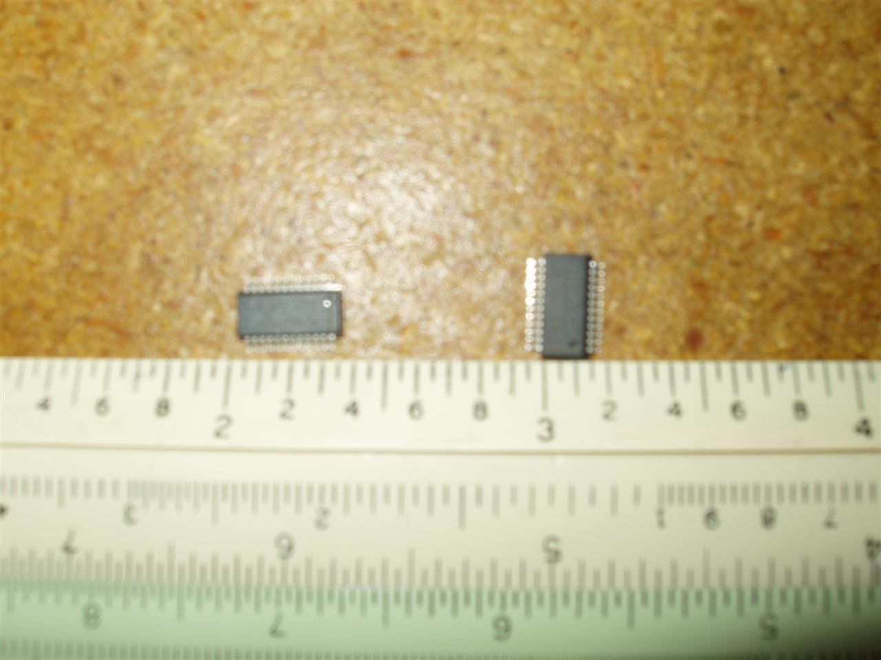
So it appears that my soldering job gets worse and worse with time.
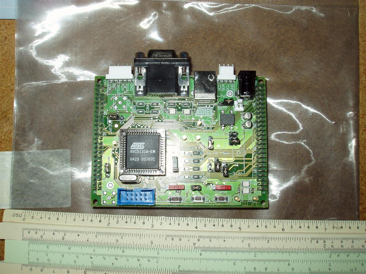
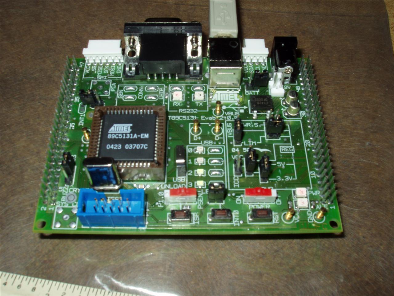
I tried doing some code testing yesterday and I kept getting feedback voltage from the 4.5V (3 AA batteries) source into the microcontroller board. Very "not good".
I measured the resistance across the pins and it had dipped about 100X since Friday (down to ~4kOhms). I tried testing with the glued chip, but it was spotty at best and after a little bit, the chip accidentally stuck to my finger more than the adapter and popped completely off the adapter.

Thankfully, I have a new soldering iron coming tomorrow from Mouser (along with some more wick and 100 feet of 4-conductor wire). I already bought a 10-mil tip in my previous order from them and this is the iron that the tip goes with, so all should be well.

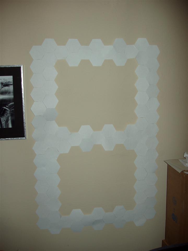
I settled in on a good size for the board. 15 pixels wide and 16 pixels high. At 5.5" on a side for the pixels, this makes the wall 3'8" wide and 6'4" high. Seems like a good size to me. A rough estimate of divider material (e.g. wood) needed is 175.5 feet. Youch. That comes out to be 48 4' pieces of wood. No only is that a lot of wood, it's a lot of weight. The outside shell should probably be wood, but the internal dividers don't necessarily need to be. I'm open to suggestions for materials, if anyone has any. It doesn't need to be super-thin (max of maybe 1" wide) and the only real requirements are that it must be opaque and must be drillable or glueable.

I spent a little bit of time fixing up the code and putting in some basic structure to deal with selecting different driver chips. Since I don't really have a good setup for testing the driver chips any more, I can only really compile it to make sure THAT works. I set up a function to deal with the 2-byte transfer method (1 address + 1 data) over TWI. I still have to make one that sends 9 bytes (1 address + 8 data) to control the LED intensity values. Just doing that really cleaned stuff up and made it so much more readable.

There won't be any more blog updates until Tuesday at the absolute earliest (most-likely Wednesday). I am taking a much-needed vacation and will be out of town until then.

Labels: , ,

Saturday, May 21, 2005

Pixels galore

What a fun two days it's been.
I got my first "OTJ" injury yesterday. I was stripping the outer casing off some 6-wire phone cord with a scalpel. I got to the length that I wanted it to be stripped to and was attempting to cut off the excess casing. I was holding the wire in my left hand and cutting with my right. I was thinking about how dangerous what I was doing was and that I really shouldn't be when the blade slipped and went into my thumb. I won't get into any details, but it wasn't very bad.

Yesterday, I made 3 pixels out of cardboard, paper, & aluminum foil. The one I used in my first test was a pile of junk and just slapped together, with bad walls (they didn't go all the way up in the corners) so I wanted to make all new ones. Here's the 3 of them all spiffy-like with lighting:


That worked just fine. Here's a video of it all:
QuickTime Video (4.2MB)

Wonderful success. Only, I ran out of resistors. I had to scrounge to make the 3rd pixel even work. So off to Radio Shack I went today and picked up a few random resistors. I redid the layout on the breadboard, as it was a complete clusterfuck of wires. It's not much better now, but there's also 2 more pixels to deal with.

Videos of the action in action!:
QT Video #1 (3.8MB)
QT Video #2 (3.6MB)

So anyway, the pixels are 5.5" on a side and 1.5" tall. I'm really liking the size of the pixels; They're pretty visible, even from a fair distance away. Plus, it would be easier to make them (slightly). The 1.5" seems more than enough. If possible, 1/2" would be great, then I could hide all of the electronics behind that in a 1-2" gap, leaving the entire structure to be 1.5-2.5" deep in total. Quite nice. I'll have to stop by Home Depot or somewhere similar to look for what I can use for wood. I remember seeing 1x3" and 1x2" pieces there. They also had 1/2x3", but it was meant for stairs and was very expensive.

At this point, I really should design the driver boards and get them off and made. I'm sorta limited right now with what I can do with the driver chips and once I get those, I can test further.

I think I will have to bite the bullet and spend $140 on a new soldering iron too. Dealing with the hassle of trying to find someone to pay to do the soldering will be far worse and I think I would probably end up spending more than $140 trying to contract it out anyway.

I think at this point, I am almost ready to start designing the actual frame for the pixels. I will have to re-evaluate how large I want to make this thing (my previous count of 159 pixels was based on hexagons... it will be slightly different with triangles) and if I want to expand the design at all.

I've also been briefly toying around with the idea of having a main microcontroller whose sole purpose is to generate patterns and delegate information to the other microcontrollers. I wouldn't be able to use the TWI for that purpose, unless I figured out a way to get the other microcontrollers to disconnect themselves from the rest of the LED driver bus, which may be a bad idea in general. There is an SPI bus on the chip as well that I could use. It's still in very rough planning at this point, mainly because I only have one microcontroller to test with.

I found an 8-channel 12-bit ADC (analog to digital converter) chip that works on the I2C (TWI) bus. This would be a much better alternative to the single-channel one I had found earlier. I could use a single one of these for each microcontroller and get good coverage for the whole wall. I might have to order up one for my next Digi-Key order.

All in all, very promising results so far. Once I get a new soldering iron, I can solder up another driver chip and start testing multi-chip communication, which should be fun.

Labels: ,

Wednesday, May 18, 2005

Holy soldering Batman!

Wow. Trying to solder a QSOP chip with a 50-mil tip is really, really hard. Like, "Don't try this at home, kids" hard.

I used a flux pen on the contacts of the QSOP/DIP adapter chip, tinned the contacts, re-fluxed the contacts, and fluxed the leads on the chip. After a couple attempts at tacking one of the corner pins to the adapter, I finally succeeded and moved onto the opposite corner. I was able to align the chip on the adapter, despite my wildly-shaking hand. I'm really going to have to do something about that if I'm going to be soldering dozens--nay, hundreds--of components.
I had to fudge around with the chip a little bit, because after tacking opposite corners, I realized that the chip was pitched up on one end, so as to not make good contact with the contacts. Using my trusty scalpel, I had to free the chip and re-mash it down on the right pins; this time, correctly-aligning it parallel to the adapter.

The soldering really wasn't much of anything except me trying to hold the iron on top of a pad (this generally resulted in the tip on top of 2 contacts at once) and then pushing the solder into the area next to the contact of the chip. I made a very concerted effort to not touch the iron to the chip leads, mainly out of fear of frying the chip. After my first attempt at soldering all 24 pins, I checked the solders using a continuity tester and found that about... 8 of the pins were actually soldered correctly. Wow...
It took me 3 more attempts at soldering the remaining pins before I finally got them all soldered to the pads. Thankfully, I had some wick around, as I needed it on at least 4 separate occasions. Solder spread across 4 pins at once is not a good thing.
Now that I had them all soldered and continuity was good, I had one last test to do: make sure none of the pins were shorted. I thought for sure that I would have shorted at least one set of pins, but a quick check showed that none of them were shorted. Yay flux! Yay me!

At this point, the only thing I was worried about was whether or not I fried the chip with heat. 700F for more than a few seconds probably doesn't feel to good to those chips. I know I wouldn't last nearly that long.

I pulled out my previous hack job (see Success!) and put this one in its place. A quick test showed that it worked great (Yippie!), and then I decided that it would be a great idea to use Monday's test along with this. So I grabbed my little makeshift pixel and hooked it up to the uC test board and... viola... instant 12-bit RGB color pixels.

Here's a couple videos (.mov) of it all in action. On the right is obviously the pixel. In the middle is the 3 LEDs I tested with in "Success!", and on the far left is the uC board with the test status LEDs.

video 1 (4.2MB)
video 2 (4.2MB)

Labels:

Monday, May 16, 2005

Color mixing

I put in another order with Digi-Key today. This order consists of the correct sizes of resistors and capacitors (hopefully). I also ordered a couple PLCC sockets for the uC as well as 3 uC's (just in case) and some other random sockets and headers I may or may not need.

My order of test LEDs from SuperBrightLEDs came in today.
I was hopefuly of the 3-color LEDs, but it turns out that the colors come out parallel, so that there's a small amount of overlap of colors, but the cones are all in a line and would never mix properly. Oh well, that's what testing is all about.
I also got 3 bright individual colors and used those to test instead. I had never really had a good setup to test mixing of colors; it was always just me trying to hold 3 different LEDs at 120-degree angles and all focused at the same point on a piece of paper while looking through the acrylic from the other side. Basically, a real hack job.
I grabbed some cardboard from a shipping box and cut out a square and then used a triangle pattern to form a triangle box to mount the LEDs. I lined this little box with aluminum foil and then taped a white paper triangle in the center. I cut slits in the middle of each of the walls, to hold the LEDs and... viola... this is what resulted:

Not especially snazzy, but hell, it works. Here's a bunch of pictures from the results of my test:


The white is kinda weak in the green and a little heavy in the red, but I think I can play around with that fairly easily. The top diffuser I used was just a white sheet of paper between the triangle box and the acrylic, so it's rather chunky and not really what I'm looking for in a diffuser.

Labels: ,

Saturday, May 14, 2005

Even more success

LED PWM control
  • OK, so I had quite a few random, odd bugs in my code... nothing enough to make the individual PWM control not work, but certainly not helping my cause either.
  • The real cause of the problem was that I had 2 "if" statements at the beginning of my code that were needed for intializing the driver chip (2 separate registry entries needed to be written to in order to get the driver chip into the correct mode). The first one was getting executed fine (sometimes), but the second one rarely (read: never) got run because the TWI operates on interrupts and the code blows by it before the interrupt from the 1st "if" block gets properly taken care of.
  • Anyway, I set it up differently, using a series of "while" loops between each step, waiting for the interrupt section to get finished before continuing on to the next config step. Then, the final step is as I had before, which is continually writing random (literally) values into each of the eight 8-bit registers (each register controls 2 LEDs).
  • By taking out all the wait loops in the interrupt code, I get quite a fast pulsing effect that's almost too much to stomach (makes my eyes hurt looking at it).
  • So now, my next steps for the code are:
    • Wire in an output port from the uC to the address pin of the driver chip to see if I can properly control the addressing of individual driver chips
    • Write up some framework for dealing with sending certain "classes" of messages to the driver chips more efficiently and programmatically.
LED color mixing
  • I actually sat down and calculated how big the resistors for each color should be (based on the voltage drop across each LED) and hooked up a test circuit to see if I could get the colors to blend again.
  • I grabbed my wonderful diffusing acrylic sheet, as well as a blank sheet of white paper, and turned the lights off to see if I could actually get all 3 colors to successfully blend into white. My first attempts weren't very good, but they were promising. The blue was WAY too powerful and the green WAY too weak (even though I was using 2 green LEDs to make up for it). I ended up basically doubling the calculated resistance for blue, as well as adding about 10% to the resistance for red, before I actually got something that wasn't an over-powered blueish white. Once I get LED's that actually match in luminosity, I think I'll be in good shape.

Labels:

Friday, May 13, 2005

Quick parts update

OK, quick update.
  • Yesterday, I received the 40 driver chips from Maxim and the 3 back-ordered LEDs from Hosfelt (they shipped those 3 LEDs in a giant FedEx box...). I haven't done anything with them yet. Probably this weekend I will though.
  • I ordered 10 each of 3 different LED colors from SuperBrightLEDs as well as 10 3-color LEDs (they were actually decently priced). I've got more testing for those to try to get the colors to mix properly.
  • I also ordered a bunch of soldering supplies from Mouser. A different soldering iron tip (hopefully, it will fit in my exisiting iron), some 15 mil solder, solder wick, a flux pen, & cleaning alcohol.

Labels:

Thursday, May 12, 2005

Success!

Awesome!...
After using wood glue between the driver chip and the adapter, bending (and smashing) the pins down, and then just straight-up pushing the chip down with my finger, I was finally able to get the driver chip to completely contact the adapter.
Check out this wonderful, sophisticated setup:


After tweaking with the code some, I was able to get the LEDs to blink. Unfortunately, all attempts to get them to blink independently failed miserably.
Another picture of the LEDs (all 3 of them) while on:


And finally, a small QuickTime video of the pulsing that I coded them up to do (slowed down quite a bit to get a more-visible effect).

Labels: ,

Wednesday, May 11, 2005

prototyping & more testing

LEDs:

  • I tried figuring out how to diffuse the LED light more. A friend sent me this link about a guy who made a color-changing tap light using 2 of each of red, green, & blue LEDs by reflecting them off a white surface first. He had a link in there to SuperBrightLEDs for getting ahold of several-thousand millicandella LEDs. From the pictures, it looks like just normal paper, but I tried that with very poor results. He said it was glossy, so perhaps, it's a piece of plastic or high-quality photo paper. I still haven't properly matched light intensities across the 3 colors, so that's part of my problem as well. I'll have to keep trying things I guess

TWI Communication:

  • On Monday night, I tried to get the TWI (I2C) communication working between the microcontroller and the LED driver chip. It was a rather hacked-up job because I taped (yes, literally taped with scotch tape) the LED driver chip to a QSOP-DIP adapter chip that was then plugged into a prototyping breadboard. In addition to the standard wiring from the uC board, I also wired in 3 LED's just to test with. I grabbed the sample TWI code from Atmel's website (which puts the uC into master transmission mode, the mode I need to use) and changed a few minor things (device address and data payload) to try to get it to run.

  • I plug everything in and get nothing... nada... great! Debug time! I remembered that the normal operation for the driver chip requires 2 bytes of data (address and value) to work properly, so I change the code to write out 2 bytes before closing the connection and try again. Same thing...

  • I've got 6 LED's on the uC board at my disposal, so I use them for status indicators. I also double-check all the wiring, because it's an easy mistake and I've done it many, many times before. I also check the continuity between the driver chip and the board, since it's just taped to the adapter chip. Everything seems to be in order...

  • ...

  • ...

  • Several hours later and several frustration levels higher, about all I'd been able to figure out is that I'm not getting an ACK signal back from the driver chip (actually, I'm getting a NotACK signal back, but I think that's what would happen if there was nothing on the TWI bus). All the wiring seemed to be correct and I'm pretty sure I got the address of the chip correct. Perhaps I'll have to try a dab of glue or something else on the driver chip to get it to hold to the adapter better. I ordered 40 driver chips from Maxim's website last week, but haven't heard anything from them other than the withdrawl of funds from my credit card, so I've only got the 2 engineering samples to test with. I've also got no other devices around that support TWI communication. Back to testing, I guess!

Labels: , ,

Saturday, May 07, 2005

component testing

Well, I spent a little time and tested the LEDs. The only 9V battery I had lying around was pretty much toast, so the LED tester didn't do a whole lot for me. I hooked 2 of the LED's up to my 4.5V test circuit that I used before and the intensity was amazing. I even think I was able to see some magenta through the sanded acrylic! Yippie!
I also tested the distance sensor. Damn, that thing is sweet. It was able to detect my hand just fine (the type of objects I wanted it to detect in the first place) and worked pretty close to the specified range. Nominal voltage was 0.2V and it peaked at about 2.4V at 10cm away. Under 10cm, it started to drop the voltage. I'm not really sure what that's all about. In the datasheet, it said the voltage is supposed to drop back down to 0.2V, but it hovered at around 1.3V.
The light sensor was really hard to test because it's a 2mm x 2mm surface mount component. I was sorta able to get it to work through some really tricky adhesive work, but the response time to go from ~4V to 0V was somewhere around 3 seconds. The datasheet has a nominal response time of < 1ms, but their test circuit had a resistor on the output pin, so that may have been my issue.
Anyway, very promising (especially the distance sensor) and hopefully, I can get a better test setup going.

Labels:

Friday, May 06, 2005

parts have arrived!

So I got both the Hosfelt and Digi-Key shipments in today. I went through and checked stuff out. There're a few things that I probably really didn't need to get, like a DIP pin aligner and a breadboarding circuitboard, but whatever...
The magnifying binoculars are pretty sweet, but I think I'm going to get a headache pretty quickly while using them. There're 3 sets of lenses that can be put in place (1 stationary, 1 that flips down from the inside, and 1 that's a single-eye piece that rotates in from the outside for the right eye) that, when all 3 are in use, do 4.8X magnification. Really intense.
I also realized that all of the capacitors and resistors were 2 or more sizes too small compared to what I need. I'll need to order a new batch of all of them. Oh well. I missed a few other things in the order and they aren't super-critical, because I can still test without them. Everything else seems to be in order and I haven't really had a whole lot of time to check stuff out yet.

Labels:

Thursday, May 05, 2005

parts and musings

I finally got a response from Hosfelt Electronics. I think they may have felt a little bad about taking so long. They shipped it yesterday (5/4) and it's scheduled to come tomorrow, so that's better. Yesterday, I also ordered 40 of the LED driver chips as well as a shit-ton of random stuff from Digi-Key. I knew I would need a lot of stuff from there and I already had a pretty big list of stuff picked out, so I ordered lots of surface-mount discrete components (resistors, caps, diodes, current limiter chip, voltage regulator), a few headers and connectors I figured I'd probably use, a bunch of tools for various tasks (tweezers, PCB vice, crimper, scalpel, breadboard, etc), and 2 sensors. I've been kicking around ideas about what else to do besides just lights. I can't really do touch sensors on a wall piece, so I started thumbing my way through the catalogue and came upon quite a variety of sensors. Two that struck my eye were a surface-mount illuminance photo-IC sensor and a distance measuring sensor. So I picked up one of each to give them a try.
The illuminance sensor measures about 1 to 3000 Ix and has a peak wavelength sensitivity of around 600nm. The wavelength response range is from about 350nm to about 825nm (visible light is between 400 (violet) and 700 (red) nm), so it reaches into IR a little bit (not a real issue, and could be rather useful). The output is analogue, so I'd need to send this through an ADC and then read off that.
The distance sensor is really quite sweet... I can't wait to get it so I can try it out. It's rather large (37mm x 19mm x 13.5mm tall), so that could be an issue, but I might be able to disguise it a bit. It's a nice all-in-one package. You just give it 5V and it outputs some voltage between ~0.5V and ~2V based on how close a "reflective" object is to it (I will need to experiment with how reflective objects need to be). The distance range for the one I ordered is 10cm to 80cm (4in to 31.5in), which is a pretty decent distance. Since this is an analogue output, I'd need to send it through an ADC as well.
What I'd like to do with one or both of these parts is place a few of them around the full pixel wall. With the distance sensors, I could have the wall react if anything came within range of it (and change the reaction based on how close the object was). Multiple sensors could be read to determine approximately where an object is (it could obviously be easily fooled). The distance sensors aren't exactly cheap either, so I would probably have maybe one every 1-2 feet.

I've been playing around some with the idea of using triangles instead of hexagons. Hexagons can really be thought of as 6 equilateral triangles (or 2, if you take the big one in the center and then the 3 smaller 1/3rds on the sides), so there's really no aleration I need to do to use triangles other than adjusting the side of them. The only thing that might be an issue with triangles is keeping the light diffused across the entire triangle face, especially in the corners. I'd have to make the walls thin enough (at the top anyway) to get color all the way to the edges.

Labels: ,

Tuesday, May 03, 2005

mini-rant

OK, so about a week and a half ago (4/21), I ordered some LED's, an LED tester, and some other miscellaneous crap from this Hosfelt Electronics place in Ohio. Later that day, someone from them called me to say that one of the parts I ordered was out out stock and if it would be OK to hold the rest of the shipment until that part came in, which she said would be "early next week." I said OK, since I still hadn't gotten my uC starter kit or any of the other components yet. Now today (5/3), I emailed them (no response yet... 12 hours later) and they haven't charged my credit card yet, which means they obviously haven't shipped it yet either. No status updates. No phone calls. No emails. Jack Shit. ugh....

I've started a spreadsheet of all expenses for this project. At some point, I will probably be posting it here, for those that are interested. Currently, the running total is around $260 (half of that is for the uC starter kit). I expect this project to cost anywhere from $1000-3000...
And, just for the record, yes, they did inspire me to start this project. "Nice idea", but disco? c'mon...
Anyway, enough of the inspirator bashing. In reality, I just wanted to make something that was different from that. Square pixels were boring to me. I really didn't have any interest in a "floor". I don't think I can really afford ~512 pixels... (no, I'm not in college, and no, I'm not living on the street... but there's just 1 of me). Perhaps, I can design it to be modular enough that I can add on to it at a later time.

Labels: ,

Monday, May 02, 2005

Pictures added

OK, here are some pictures of the latest schematic and PCB layout top, bottom, and top+silkscreen layers. The size of this board is 2"x2", as stated in the previous post. There might be some minor tweaks to this, but it shouldn't be too drastic.

Here's a pic of what the hexagon wall currently looks (1:1 scale made with paper). The center would obviously be filled, and this is 11x14.5 pixels:


Here's a couple more pics, of the board and the engineering samples of the LED driver chips I received. Yes, 32 of those tiny chips need to be soldered! Markings on the ruler are inches, with tenths of inches in-between.


These two pictures demonstrate the before-and-after of my wonderful sanding job on the acrylic. If the pictures were better, they would demonstrate how much translucency it lost after sanding it. You can also see a slight hint of yellow in the last picture (which is what I eventually would want out of red and green LED's. The LED's I'm testing with are just pieces of crap that I had lying around.

Labels:

Initial Post

This is the first post for a project I'm working on. The title is mostly a placeholder, as I haven't really figured out a name for it yet.

Anyway, the idea for this project is to create a wall hanging (or perhaps floor-standing that is next to a wall, depending on size and weight) that consists of semi-large pixels using discrete RGB LED's.

This post is going to be really big since this is about a month's worth of ideas coalescing into one post.

Current state of the project:

Physical:

  • Since I've decided on regular hexagons, I also have to deal with the whole square-root-of-3 issue involved. Basically, if a hexagon (if measured from one side to its opposite) is, say, 4", then each side of the hexagon ends up being 2*side/sqrt(3), or 8/sqrt(3), or approximately 4.62" (4.6188021535170061160731902440157...). All the measuring I'm going to be doing are approximations anyway, so this shouldn't be too much of an issue.
  • I'm almost positive that I will be making the pixels hexagon-shaped. This has several issues, compared to square pixels. Square pixels can be constructed fairly easily using long, straight runs of whatever building material is used. Hexagons need to have lots of individually-cut pieces attached to something (most-likely a firm backing in my case) attached at 120-degree angles.
  • I've settled in on hexagons that are 3.5" across (each side is just over 2"). This seems a decent size (10.6 sq. inches) and a happy medium between constructability and nice, small pixels. As the size of the hexagons gets smaller, the structural integrity of the walls between the pixels becomes less and less.
  • For the overall size of the wall, the size I've kinda accepted is 11 wide by 14.5 tall. So, first of all, an explanation of how that even makes sense. Take a regular hexagon (any will do... they're all the same) and orient it so that two of the edges are parallel to the ground. This is how all of them are oriented. Now, take a single hexagon and then place another identical one to its right, one-half pixel above it so that a single of the diagonal edges from each of them are abutted. Now, take another one and put it one-half pixel below the one that was just placed, so that there is a single edge's length distance between the 1st and 3rd pixels. Continue doing this for 11 pixels and this is how wide it is. Do this for 14 times and then take an additional 5 pixels and place them at the bottom of it, so that if the whole thing was folded over, the top and bottom edges would line exactly up. This gives us 11*14+5 = 159 pixels for the entire display.
  • I still haven't figured out what to make the walls between the pixels, or how big they should be. I'm open to any suggestions. Wood would be the cheapest, but since I'm working with slightly small pixels, I need to keep the width of the wood narrow. This doesn't work to well with wood, but as long as I would use nails and glue instead of screws, I should be OK.
  • For the outward-facing window, I found a 7'x3' piece of 1/4" acrylic at Ax-Man (I was lucky to find it). It's irregularly-shaped and about 2' of the 7' aren't really usable for a top window, so that leaves me about 5'x3'. That's fine because I can have a decent piece to test stuff out with. I also picked up some coarse- and fine-grain sandpaper blocks to use at improving the diffusivity of the acrylic. It's normally completely clear (which is what you want most of the time), so I tested sanding the clear surface down and it seems to have worked decently. I might be playing around with different things, based on how well the 1/4" works.
  • I've come up with a way to map square pixels into hexagonal pixels. There's a small amount of distortion (each square pixel is stretched horizontally by about 15%) because of the whole square-root-of-3 issue again. Basically, the hexagons are split into two groups: the A-set and the B-set. The A-set gets its shade from 2 side-by-side square pixels. It takes 5/6 of the color from one and adds it to 1/6 of the color of the other to get its approximated color. For the B-set, it is slightly more-complicated (because of the half-pixel offset). Each B-set pixel gets its color from a 4-square of square pixels. It takes 5/12 of one pixel, 5/12 of the pixel directly below it, & 1/12 of each of the two remaining pixels.
  • Now, naturally, this will look like ass on anything but a large number of pixels with a small size. So why do it at all you ask? Why even do hexagonal pixels at all? Because they're cool. That's why. Also, you can get some nice radial patterns with them, instead of the jaggy ones you see with square pixels. Hexagons are a better approximation of circles (the tightest packing of circles in a 2-d space is the same as what hexagons end up being) and they're one of the 3 regular polygons that tile perfectly with just themselves (equillateral triangles and, of course, squares are the other two). There are 3 straight lines of pixels, as compared to just 2 with squares. Granted, they're all at 120-degree separations from each other, but there are 3. Plus, squares are too easy. How am I supposed to have fun with bland-looking squares? Everything we look at is rectilinear, so why not spice it up a bit, huh? That's what I thought. So why not equillateral triangles then? Mainly, because I haven't really thought about it until now. After careful consideration, I'm not really sure myself. I will have to keep that in mind.
Electrical:
  • After "much deliberation" (a.k.a. very little), I've decided to use Atmel's AT89C5131A-M microcontroller (uC). It is a USB C51-based Microcontroller with 32K Bytes Flash, 1K Byte Data EEPROM, 1280 bytes RAM, 7 USB Endpoints (not entirely sure what this means yet), TWI (Two-Wire Interface), SPI (Serial Peripheral Interface), UART (For RS-232), PCA (Programmable Counter Array). Of main use to me are the USB interface and the TWI (explained below). This will handle all of the signals to/from a computer and then dish other signals out to the LED drivers (over the TWI).
  • For my LED driver setup, I've decided to go with Maxim's MAX6964. It's a 17-output LED driver with 4 per-channel bits of intensity control. It can sink up to 50mA per output, or 350mA max (for my uses, it will be a limit of 20mA per output). It accepts signals over a 400kbps TWI (hey, how about that... the uC I've chosen has just such outputs... I wonder if they're compatible...). What's annoying about it is that it's in a 24-pin QSOP surface-mount package (that's 25 mil [1 mil = 0.001"] spacing between the pins).
  • I've ordered a few different intensities of LED's to test with, so I still haven't figured that out quite yet. No real updates here.
  • To go along with the uC, I ordered (and received) a starter kit (AT89STK-05) through Digikey. The board is a pretty sweet package. It's roughly 4"x3", has RS-232, USB, TWI, SPI, and "LPC Test Mode" (not really sure about the uses for that) connectors on it, as well as 2 48-pin headers for pretty much every pin on the chip (and board) and a DC-in jack and a vertical header for a 9V power supply. There's an on-off switch, a switch to tell FLIP (explained later) how to put the data on the chip, a reset, INT0 (interrupt), ISP (In-System Programming), and USB Unload buttons for various testing purposes. There're 2 LED's for general status indication, 2 LED's for the RS-232 port (Rx & Tx), and 4 general-use LED's that are tied to some of the P3 output ports. The entire thing is clocked with a(n included) 16 Mhz crystal. All-in-all, a pretty good investment. I can do most of my testing directly with this board, instead of kludging up something on breadboard.
  • The starter kit board came with FLIP (the acronym meaning eludes me and is meaningless anyway), which is Atmel's programming utility. You have the ability to program it directly through the USB port (it's also powered off the USB port). No need for RS-232, PIC programming socketes, or higher voltages. Fuck that bullshit.
  • I have come up with the beginnings of a board to use in the actual wall. No way am I going to use the starter kit board in the actual installation. Because it was free, I have been using ExpressPCB's software to design the schematics and PCB. They are sorta tied together (you can load the schematic you created in ExpressSCH with ExpressPCB) and it will highlight pins on the same net, so you can visually check it for errors. The board I've got layed out is in a nice 2"x2" space, with 4 1/8" mounting holes in the corners, the PLCC-52 socket for the uC; a USB connector; a current limiting circuit for the USB port; a voltage regulator (to bring any power down to 3.3V); an external voltage input header; a crystal socket; power & ALE status LED's; TWI header pins; reset, SPI, & USB Unload buttons;regulated power, ground, & reset signal header; a switch for selecting the voltage source; and a power switch. Almost all of the design is taken directly from the starter kit electrical schematic drawings. Kudos to them for providing it. Pictures will come as soon as I get somewhere to put them.
  • With 159 pixels and 3 LED's per pixel, that makes 477 LED's. Each driver chip supports up to 17 LED's. So My current approach is to do 5 pixels per driver chip, making 15 LED's per chip. 159/5 = 31.8, so I would need 32 driver chips. Each driver chip can be one of 4 unique addresses, so that would "normally" mean that I would need 8 uC's to drive the entire wall. This is A) ludicrous, B) expensive as hell (at ~$10 for each uC chip), and C) way overkill for what the uC can do. But wait, there is hope! The pin that defines the address to be used can be set to power, ground, or one of the two signal pins. Hm... what if I just connected an output port from the uC directly to this port and then just normally set each port to ground and then pulled up each driver chip individually to power as I need it. That way, I can even send the same signal to multiple driver chips at the same time! (You'd almost think I thought of this before or something). As luck (yeah... right... luck...) would have it, there are exactly 32 usable output ports on the uC (there are 34, but I am using 2 for the TWI). So with the size of the wall at 11x14.5 pixels, I can use exactly 1 uC to drive the entire thing. Crazy how it all falls into place like that ;)
Programming/System Integration:
  • I really haven't done much in this arena yet, as it's the section that's the furthest away and the section that I'm least-worried about. I wrote a quick program in C (yay... no need to learn C51 assembly at this point) to randomly (using a wonderful 15-bit pseudo-random number generator in their stdlib library) turn the LED's on the board on and off. Very cool and very simple.

Labels: