Jurek and the Amazing Techno, Colored DreamWall

Jurek and the Amazing Techno, Colored DreamWall

The title is mostly a placeholder, as I haven't really figured out a name for it yet. This project is a wall hanging that consists of semi-large triangular pixels using discrete RGB LED's and PWM to control intensity levels of each LED, resulting in a 4096-color display.

Saturday, February 25, 2006

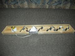
Pixel row test setup

Over the last week (and mainly just today), I've been trying out some methods of creating the internal divisions between the pixels in a given row. I already built a single 15-pixel row earlier to start things off, so I've been using that as my test vehicle.

I bought some flashing from Home Depot to do the separators (as I stated in the previous post) and cut a 2' strip. I then cut it in thirds lengthwise, giving me 3 pieces 2' by slightly less than 2".
I screwed up the first piece pretty early, as expected, and then actually thought ahead about how to cut the 2nd strip before actually cutting it.
The second strip worked out well, except I couldn't measure correctly and ended up with a zig-zag piece in which every straight length was 1/4" too short. I also had a hard time actually attaching the metal to the plywood. The nails (carpet tacks, actually) I bought are absolutely tiny and the only way I could pound them in is by using a needlenose pliars to hold them. The hammer head barely fit into the box and I kept hitting the flashing with it too. And on top of all of that, the plywood just absorbed all of the force of the hammer because it was being suspended by the walls.
The 3rd strip actually worked out well. The 2' piece I had cut ended up being about 2" too short for what I needed, but that was fine as I really didn't need to test a whole 5 pixels or anything. I used a 1/16" drill bit and pre-drilled into the flashing and a small amount into the plywood to use as a pilot hole. Then I used a (very) small amount of wood glue on each carpet tack and just pushed it in with a pliars instead of with the hammer. This worked considerably better than my first approach. I need to pick up a punch though, because the pliars can only push so hard and I need to get the nail/tack more flush than it currently is.

I just used my LED tester to wire up RGB LED's, mainly because it was a lot easier than any other method. The red was overpowering the green and blue so much (with all 3 at 10mA) that I dropped the red down to 5mA. This worked out surprisingly well.

I also experimented with the 1" border between each of the pixels, just to make sure that everything still jibed with my earlier design work. I used black duct tape (I couldn't find my electrical tape) and lined everything up properly. I think it looks pretty decent.

Here are some pictures of the whole thing:
Test pixel row, with 1 pixel lit up white:


The guts of the row, with the pixel on still:


3 of the pixels, close up, with carpet tacks visible:


Pixel mask with 1" borders (the only border that is 1" is the common section between the two; Using an incandescent lightbulb for backlighting):

Labels: ,

Monday, February 20, 2006

Miscellaneous updates

Bookkeeping
I've added a bookkeeping .xml file to the site, so everyone can see exactly how much money I've wasted on this glorious hobby. It is under the links section.

"Other"
I bought some flashing today and a metal scissors to cut it with. I have yet to test it out; I will be doing that shortly. The idea is to use the flasing as a barrier between the 15 pixels (or 30 in the double row) of a row. Then in order to compensate for the pixel wall thickness differences, I plan on painting/coloring/etc the inside of the acrylic to be the correct width. This will also give me a little bit of slop for positioning the flashing, as I don't need it to be exactly on the pixel line.

Yay progress!

Labels: ,

Thursday, February 16, 2006

Hoo-Ah! SpokePOV & uC board

Spoke POV
A friend was borrowing my digital multimeter, so I couldn't use it to test any of my soldering while working on the Spoke POV kit. In the kit, there are:
  • 60 LEDs (2 leads each)
  • 1 20-pin socket
  • 1 8-pin socket
  • 8 16-pin IC's
  • 1 3-pin sensor
  • 1 4-pin switch
  • 2 10-pin headers
  • 4 2-pin battery clips
  • 5 resistors (2 leads each)
  • 8 10-pin resistor networks
  • 1 25-pin DB-25 connector

For those of you doing the math at home, that's 426 through-hole leads to solder without a continuity tester. I flew through everything with relative easy; I was having a harder time aligning all of the LEDs to be straight than I was with any of the soldering. I didn't even need to use my binoculars to do it! It took me about 2 hours or so to solder everything up on both the dongle and the main board and then I crossed my fingers and plugged it all into my computer. Huzzah! Success on the first try.

Board:


Action Jackson shot:


Microcontroller Board
I got bored last night and decided to finish soldering the few remaining components onto the microcontroller board I left unfinished some 5 months ago. I had to solder on a resistor, 2 capacitors, 2 ADC chips, the CPU socket, the USB connector, and 8 headers. It all went fairly smoothly and I was a little surprised that I hadn't lost the soldering touch yet. Yay me. I still didn't have a mutlimeter to test when I did this, which is slightly scarier considering the ADCs are 16-pin chips with 0.65mm pitch (a hair wider than 25mil pitch). Anyway, I got a new multimeter shipped today and I did a quick test of the pads and everything seems to have worked out OK. Anywho, here're a bunch o' pics:


Labels: ,

Wednesday, February 08, 2006

Preparation time

I spent some time cleaning off my work area the other day. It was beginning to become infested with legos and various other small projects' paraphernalia. I'd say that at this point, it's about half ready to be used again. I have some ideas about building some storage shelving on the underside the desk (it's just a couple pieces of chip board, basically, so there's a lot of room for improvement) so I can offload some of the tools and storage bins that have no real good place to go yet.

I have also ordered up a little side project for coolness' sake and to see if I can kickstart my interest in the electronics side again. This site is for a bike LED POV project and she has everything you need to make it except the tools and solder available to buy. It's fairly cheap, at around $50, so even if it doesn't work (I fully expect it to work, though), I won't be out a big chunk of money.

Labels:

Saturday, February 04, 2006

Whoah!

Holy oh-my-gosh! He actually updated something!!!

Yes, lo and behold, I have actually started working on this thing again. I spent about 2 hours (I know, not a whole lot of time) doing some woodwork for the framing of the wall. I made some decent progress, especially considering there hasn't been any for about 5 months.

I had decided way-back-when that the 3" high outside wall boards I had purchased just weren't going to cut the mustard and bought a whole bunch of 4" high pieces. I spent all of my time today cutting the 4" pieces to match and replace all the 3" pieces I already had cut.
Then I started assembling an entire pixel row (in total, consisting of 3 outside pieces, 1 inside piece, and 1 floor piece). It's not the best construction, but I tried some things out and figure out what will and won't work. I used small brads to nail the outside pieces to the floor piece (seeing as the floor piece is plywood and not thick at all). This only worked "OK", as the plywood split very easily. I may have to find another method of attaching them all together.
For attaching the internal board to the floor board, I used 4 angle brackets. Perhaps it's a little overkill, but at this point, it's all just testing anyway. The end product isn't horrible and makes me feel like I've actually accomplished something, rather than just cutting random pieces of wood.

Stay tuned!! Please!!

Labels: